What's new in artificial lift
Artificial LiftWhat's new in artificial liftPart 2 – Fourteen new downhole/ surface system developments from 10 companies/ organizations for electrical submersible pumping and other artificial lift operationsJames F. Lea and Herald W. Winkler, Texas Tech University, Lubbock, Texas; and Robert E. Snyder, Executive Engineering Editor
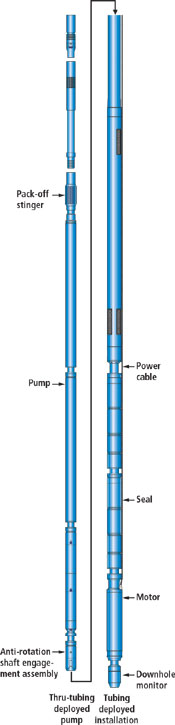
Part 1, presented last month, covered 15 recent developments in four categories of artificial lift technology: beam and progressing cavity pumping (PCP), plunger lift and gas lift. This concluding article introduces 14 new developments from nine companies and one research council. Eight of the presentations include new downhole and surface equipment for ESP systems. The remaining items cover contributions for various artificial lift and production operation categories, such as new ideas for: a pumping system, coiled tubing, well testing and well control. ELECTRICAL SUBMERSIBLE PUMPS (ESPs) Described here are eight equipment and instrumentation/ software developments including: a through-tubing conveyed ESP; a variable speed drive; an ESP shroud hanger; sensors for downhole and surface interface; downhole desander, motor protector and gas handling systems; and an ESP bypass tool. Through-Tubing Conveyed ESP. Baker Hughes Centrilift, Claremore, Oklahoma, has introduced the Centrilift Thru-Tubing Conveyed (TTC) ESP system which provides an innovative approach to economic well completions. By eliminating the need for workover rigs, it reduces operating costs and well downtime. The system is designed to install and pull the submersible pump assembly without a conventional workover rig, Fig. 1. Pump installation and removal can be accomplished using a variety of methods, including: wireline, slickline, electric line, coiled tubing, small-diameter tubing and sucker rods. Systems are operating in 4-1/2-in. tubing, with larger system deployment capabilities under development. TTC systems use standard Centrilift ESPs. The new technology has numerous benefits, including: reduced workover costs on pump-only failures; reduced cycles in and out of wellbores give increased power cable longevity; economical pump replacement in response to real-time changes in well dynamics; and less-intrusive workover procedures, ideal for environmentally sensitive areas. The system uses standard Centrilift components. Applications that can benefit include: small offshore platforms without permanent rigs; remote locations with logistical problems for workovers; environmentally sensitive areas or urban well sites; and any high-cost workover environment. Wells with production strings 4-1/2-in. or larger are candidates. With average workover costs on Alaska's North Slope running between $140,000 and $240,000 per day, fields have high workover rates. The first unit was installed in a well in a North Slope field in late 2001. The project, which initially deployed TTC technology in 4-1/2-in. tubing, resulted in cost savings of at least $100,000 per pump change-out.
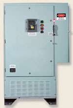
Variable speed drive. Centrilift introduces the GCS ElectroSpeed II , the only variable speed drive (VSD) in the industry to offer a choice of six-step or filtered pulse wave width (PDM) output waveforms. The patented filter controller protects the motor by either switching to six-step mode or shutting down the unit if the filter fails. On the input side, the system offers standard 6- or 12-pulse converter input options. Drives with higher pulse count converters can be special ordered to meet IEEE 519 Standards for increased harmonic reduction.
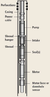
The VSD has a range of 66 kVA to 2,000 kVA. It is designed for easy setup/ operation, with advanced features that reduce the number of circuit boards and enhance drive reliability/ versatility. The system's enclosures can be customized to meet the harshest environmental demands, Fig. 2 The new VSD is a fourth-generation drive representing over 25 years of ESP-specific experience. Surface controllers are an integral component of ESP systems. VSDs offer many advantages over constant-speed controllers by allowing operators to vary ESP operating parameters to: control motor speed to lower motor temperature; improve gas handling; control well drawdown; adjust ESPs to changing well conditions; and decrease startup stresses. Positive-seal shroud hanger. Motor shrouds and shroud hangers are commonly used to set ESP systems below well perforations to maximize well drawdown and/or to minimize gas interference in the pump, Fig. 3. The shroud orients wellbore fluid around the downhole motor, thus helping to cool it.
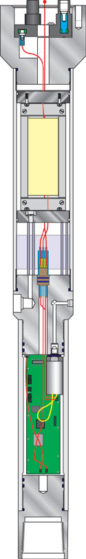
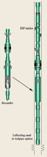
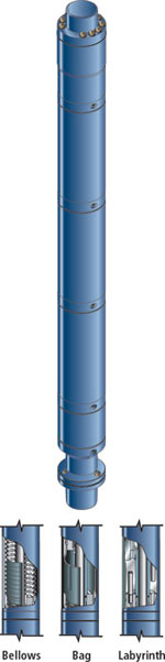
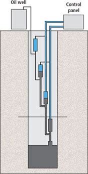
Conventional shroud hangers often create multiple problems, including: misdirected fluid flow which creates motor heating; excessive heat causes scale buildup between motor and shroud; optimum water production and well drawdown are not achieved due to scaling; poor gas separation occurs due to fluid/ gas leakage through the shroud hanger; and gas production can be below expectations. Further, wells can continually shut down due to high temperature affecting motor performance; and scale-restricted fluid flow can create additional heat and cause eventual motor failure. Downhole re-circulation systems have been only marginally successful in solving these problems. Testing performed at Wood Group ESP, Oklahoma City, determined that wellbore fluids and gas were leaking through the conventional shroud hanger, and leakage increased at very high rates, as flow between shroud and motor became restricted. Based on these findings, a new intake body and shroud were designed. The new, patented-design, positive-seal shroud hanger: efficiently forced wellbore fluid past the motor; reduced motor temperature 30°F to 50°F; reduced scaling; allowed for more accurate equipment sizing, which in some cases lowered the HP requirement by 50%; provided better gas separation; increased drawdown efficiencies; and increased equipment run life and production. Downhole sensor/ surface interface. Wood Group ESP has introduced the new SmartGuard V and SmartGuard VI downhole sensor and surface interface systems for ESP systems, Fig. 4. These enhanced models offer expanded monitoring of vibration and leakage. SmartGuard monitoring systems enable operators to reliably and accurately monitor the condition of their ESP systems, and track wellbore parameters. All of the systems monitor wellbore or pump intake pressure, wellbore or intake fluid temperature, and pump motor oil or winding temperature. The new models also measure vibration of the pump system and current leakage, which allows cable degradation to be determined. The SmartGuard VI model includes the measurement of pump discharge pressure. The system can be installed on all major brands of ESPs. The sensors have been used successfully as part of an integrated control system that automatically cycles wells off and on based on predetermined parameters. The system is programmable to sample data continually with selectable recording capabilities. Downhole desander system. ESP systems specialist, Pumptools, headquartered in Aberdeen, has launched its SandCat system, which separates sand from the produced fluid in sandy oil wells and prevents it from entering the ESP, thus reducing destructive consequences. The system is a downhole centrifugal sand separator connected below the ESP that separates sand from produced fluid, allowing non-abrasive fluid to the ESP, Fig. 5. Costly well preparation methods such as sandscreens and gravel packs are avoided, as it can also be retrofitted to any ESP well. The sand management system includes unique calculation software to predict separation efficiency on a well-by-well basis. The supplier provides this service for all SandCat applications to determine the appropriate system spec. Available for flowrates up to 10,000 bpd, the tool comes in sizes suitable for casing sizes from 5-1/2 in. to 9-5/8 in., and is custom engineered for each installation. Unique software enables the well engineer to calculate efficiency required of the system on a well-by-well basis, and predicts how much sand is being separated and, therefore, allows the operator to decide on the best sand management option. The tool separates the sand before it enters the ESP, leaving it downhole and collected either in a tailpipe, or dumped into the rat hole below the perforations, to be removed in a later workover. Pumptools offers four different deployment methods to optimize sand separation management. ESP motor protector. Advanced motor protector systems from Schlumberger, Houston, are designed to handle challenging environments. They are available in different versions to provide a fit-for-purpose solution for sand and solids production, corrosive fluids and high-temperature environments. The new design features an optional metal bellows to replace the elastomeric bag, Fig. 6. Using metal bellows extends temperature operating limits far beyond those of the bag-type protector. In the case of gassy wells, the bellows also prevents gas from migrating through the rubber bag and displacing the motor oil. The bellows is resistant to H2S and impermeable to gas and, thus, is more suitable for wells in harsh environments, i.e., high temperature and H2S, as well as high gas content. The advanced protector has special features for wells producing sand or solids, including a novel protector head design. This allows falling sand or solids from the protector intake to drop back into the wellbore while protecting the top shaft seal from abrasion damage. It also utilizes new bearing types to improve shaft stability and reduce abrasive wear. If temperature, gas content and corrosive chemicals are not a concern, the metal bellows can be replaced with the traditional elastomeric-bag of labyrinth-type design options, while still incorporating advanced options to handle abrasive environments. With a maximum temperature rating of 425°F, the high-temperature, advanced protector has a proven record in steamflood injection applications at its maximum operating limits. These wells would have never been produced with ESPs at maximum rates before development of this new protector. Gas-handling system. Schlumberger's Poseidon gas-handling system is a multiphase, axial flow device installed below the production pump of a Schlumberger ESP to handle up to 75% free gas through the pump. The system can be installed above a gas separator when gas can be vented into the casing, or it can be installed above a standard intake if all produced gas must go through the pump. It can also be used in subsea wells and wells with nonvented packers. The axial flow stages prime the main production pump and push the gas-liquid flowstream into the stages. Gas volume is reduced by compression. Lab tests and field installations have shown that it can successfully operate in the ultrahigh-gas-cut ESP market with gas volume fractions up to 75%, far exceeding conventional systems' 40% to 45%. Fig. 7 shows before and after ammeter charts documenting improved pump performance with the new system's installation.
The first field installation was in Colombia in a field operated by HOCOL, one of the Mimir Companies. Well SF-75 is in a block relying on water-alternate-gas injection at fixed intervals to improve secondary oil recovery. The injection program causes frequent high variations in the produced gas. The system was operating with a gas-handling device, but production significantly dropped with gas increases. After change-out to the Poseidon system, high and steady production rates were achieved at higher gas volumes. The system improved pump efficiency in handling free gas. The well's production increased by more than 40%, and the new installation managed free gas rates as high as 60% in the pump intake.
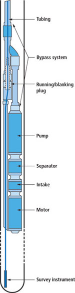
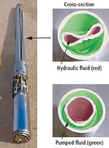
ESP By-pass Tool. There has been a need for a downhole ESP companion tool by which BHP, BHT and production logging data could be obtained in both producing and static conditions. Monarch Engineering of Gardena, California, designed a bypass tool, through which reservoir data could be obtained. This tool, in its original design, is available from Oilwell Survey Testing Systems (OSTS), Santa Fe Springs, California, Fig. 8. The tool's key features are its: simplicity; friendly wireline operation; attractive cost; and trouble-free long life. The tool body is fabricated/ machined from plain-end mechanical tubing. The side arm for hanging the ESP is certified welded to the main body. The instrument tubing is drawnover-mandrel mechanical tubing in Range 2 lengths with a flush joint thread. It is hung (pin end up) from an oval swivel connection just below the blanking plug seat. This connection permits orientation of the instrument tubing to fit the OD of various series of ESPs. The blanking/ running plugs are 1-3/4 in. or 2-1/4 in. The seat for these plugs will pass 1-11/16-in. logging tools. The tool is available in 2-3/8-, 2-7/8-, 3-1/2- and 4-1/2-in. sizes, with 1-3/4- or 2-1/4-in. blanking plug. It is available in stainless steel. MISCELLANEOUS Six items under this category include: an electric hydraulic ESP; a capillary string coiled tubing unit; a staged compressed air-lift pump; a riser-deployed test system; a gas well deliquefying pump; and a stripper well pump-off controller. Diaphragm-type ESP. Smith Lift, LLC, Provo, Utah, a subsidiary of Smith International, Inc., is introducing a new submersible pump line that has been in development and testing for the past three years. The pump is similar in size to conventional submersible centrifugal pumps, but uses a patented, true-positive-displacement diaphragm pumping system to improve efficiency, handle solids and pump mixtures of gas and liquids. The pump, known as the Hydraulic Diaphragm ESP (HDESP) provides a downhole electric-driven hydraulic system that powers a hose-like “diaphragm” to positively displace formation fluid into the production string, Fig. 9. The current pump design is 3-3/4 in. in diameter, 10 ft long and weighs less than 150 lb. Versions are designed to produce 50 bfpd to 400 bfpd from depths of up to 6,000 ft.
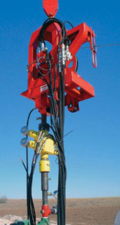
The new ESP has been used to move a wide variety of fluids, from heavy oil to fresh water, under a wide variety of fluid conditions, including up to 2% sand/ coal fines, gassy fluids and high H2S/CO2. The pump is constructed of stainless steel and is installed similarly to a conventional submersible centrifugal pump. Chemical treatments, such as acidizing and paraffin solvents can be accomplished by the operator with the pump in place. The pump typically consumes about one-third of the power required to drive a conventional rod or centrifugal pump, and, due to the ability to pump off, more fluid production is typically achieved, especially in high gas situations. Capillary coiled tubing unit. State-of-the-art Capillary Coiled Tubing Unit (CCTU) equipment for the application of capillary-string artificial lift has been developed by Weatherford, Houston, Fig. 10. A common concern among operating companies with regard to capillary string installations is safety – a proactive response resulted in safe, reliable equipment. Using uniquely designed equipment, this unit fully integrates functional hydraulic 10K-psi working pressure BOPs into everyday service, installation and application.
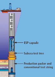
The 1-1/2-in., 10K – psi BOP system contains a stripper head with a dual stack of rams. These shear-blind and pipe rams are capable of working with standard 3/8-in. and 1/4-in. stainless tubing. The unit has a self-contained actuator with sufficient volume to meet API cycling specs. The BOPs can easily be modified by adding special adaptors that allow them to connect to existing capillary hangers that may be already in place on wells from previous installations. The BOP mates with the top of Weatherford-installed capillary string hangers. Along with the safety benefits of the system come some mechanical benefits. The operator's permanent capillary hanger never sees the wear and tear of constant stripping of tubing through it. Typical rig-up/ rig-down time is about 30 min. Airlift oil pump. Airlift Services International (ASI), Anderson, Indiana, has developed and field tested the Airlift Oil Pumping System, a new oil pump that lifts oil to the surface using compressed air. The pumps are being tested in wells owned by Energy, an Indiana-based company of ASI. The system lifts oil by moving it from stage to stage with compressed air. Fig. 11 shows a 1,000-ft well with an Airlift pump shown schematically as four separate, 150-psi compound air pump stages – actually within one string – connected with the air supply lines. The system uses 150 psi of compressed air to lift the bottom stage first, and then through all the other stages above it until the oil is in the tank. Initial testing results of the third-generation pumps on oil wells owned by Energy show it has reduced downtime from 6.9% with the traditional pump to 1.7%. In March 2004, Airlift will further enlarge its Illinois test site with a 3,000-ft well which, if successful, will greatly expand its potential market. To date, the deepest the system has worked in is about 1,600 ft. Deepwater reservoir test system. Baker Hughes Centrilift, Claremore, Oklahoma, has designed a riser deployed, deep- and ultra-deepwater reservoir test system utilizing a variable speed drive and an encapsulated electric submersible progressing cavity pump (ESPCP) set in the riser just above the subsea test tree (SSTT) as part of the test string, Fig. 12. This unit is intended for deployment in water depths of 1,000 m to 3,000 m (3,300 ft to 9,800 ft) and is capable of producing 500 bfpd to 1,000 bfpd of 15°API crude or lower. The Riser Deployed Test System (RDTS) was developed because exploration investment is often dedicated to deep- and ultra-deepwater reservoirs. And operators targeting these reserves need to optimize extraction of heavier grade crude to reduce well testing costs. The new system offers an advantage by eliminating the need for an ESP packer, BOP can, and associated electrical penetrations. Deployment begins by setting a conventional production packer and sealbore at depth, above the zone of interest. A bottomhole assembly uses a seal assembly suitable for the production packer, and a conventional test string with samplers, recirculation valves, etc., below the SSTT. The capsule is assembled with the ESPCP inside, made up into the string above the SSTT, and tested to 5,000 psi to ensure pressure integrity. The central string in the capsule also contains a sliding sleeve (conventional or hydraulic) which can be opened to either flow the well naturally or circulate fluid past the ESPCP. The capsule can also be constructed to accommodate a by-pass to allow wireline or coiled tubing intervention below the ESPCP. Fluid flows from the formation into the test string, entering at the bottom of the capsule; it is then drawn into the pump intake and produced to surface. Gas-driven pump. Liquid loading is a common production problem in natural gas production. This is because reservoir liquids (oil, water, condensate) are transported with gas in a two-phase flow, which is an inefficient use of mechanical energy. The Alberta Research Council, Edmonton, has proposed and patented a new downhole pumping concept, Fig. 13. Gas and liquid phases are separated, with the gas used to drive a pump to transport the liquid to surface. This concept utilizes the potential energy stored in the reservoir more efficiently and results in higher recovery factors. To date, the feasibility of this pumping technology, along with a reciprocating-type pump application, have been investigated theoretically and experimentally with a lab prototype, in collaboration with the Department of Mechanical Engineering at the University of Alberta. Development is ongoing with the design and construction of a prototype pumping device for field testing. Pump-off controller for stripper wells. Lufkin Automation, Houston, is testing new technology to apply pump-off control (POC) on stripper wells. POCs have been used for years on rod-pumped wells, but many operators have not justified them on their strippers. The company has taken the SAM Well Manager platform used on thousands of wells and incorporated its DSC (Derived Surface Card) Technology. This new unit is basically a POC that controls using the surface dynamometer card with the industry-standard, single-set point control, but without use of a load transducer. The DSC technology – invented/ patented by Nabla (acquired by Lufkin) – has been put into a new product named the SAM Economizer. This is a reduced SAM Well Manager that uses Lufkin Hall Effects Transducers on the motor and crank to derive the surface dynamometer card. While not intended to be as accurate as a load-based POC, and thus not able to provide accurate downhole optimization analysis, it will handle simple on-off control based on the card shape, Fig. 14. Of course, it is recommended that, if an operator is concerned about loading or true analysis, it should use a load-based downhole card controller. The new system will record the last 60 days of run time, 24 hr of on/off cycles and pump-up/ shut-down cards. As with the Well Manager, the Economizer is SCADA-ready and uses a pocket PC or laptop as the local interface. It also has a two-line text LCD for quick well status. It is being tested in several areas and is to be released before mid-2004. This will be the first stripper well controller that is user friendly and based on proven technology. Typical payback will be weeks to a few months, based on the usual POC savings of reduced electrical usage and well failures, and increased production.
|
|||||||||||||||||||||||||||||||||||||||||||||||||||||


- What's new in production (February 2024)
- U.S. operators reduce activity as crude prices plunge (February 2024)
- U.S. producing gas wells increase despite low prices (February 2024)
- U.S. oil and natural gas production hits record highs (February 2024)
- Dallas Fed: E&P activity essentially unchanged; optimism wanes as uncertainty jumps (January 2024)
- Enhancing preparedness: The critical role of well control system surveys (December 2023)
- Applying ultra-deep LWD resistivity technology successfully in a SAGD operation (May 2019)
- Adoption of wireless intelligent completions advances (May 2019)
- Majors double down as takeaway crunch eases (April 2019)
- What’s new in well logging and formation evaluation (April 2019)
- Qualification of a 20,000-psi subsea BOP: A collaborative approach (February 2019)
- ConocoPhillips’ Greg Leveille sees rapid trajectory of technical advancement continuing (February 2019)

