Qualification of a 20,000-psi subsea BOP: A collaborative approach
The term high pressure, high temperature (HPHT) is codified in the U.S. Code of Federal Regulations to mean any equipment with greater than 15,000-psi-rated pressure and/or greater than 350°F rated temperature, intended for wells with these conditions. The new HPHT development paradigm, as described in API 17TR8, has been applied recently to a variety of subsea equipment, such as wellheads and production trees. To meet the higher qualification standard, designers have adopted new processes with regards to specifications, materials qualification, verification, validation and independent third-party review (I3P).
While there are no particularly unique physical design conditions associated with HPHT equipment, the higher pressure and/or temperature ratings, combined with the environmental effects of wellbore fluids and subsea operation, have driven the industry to focus a high level of engineering resources to accomplish the design goals.
A modification of the general HPHT framework is now being applied to a 20,000-psi blowout preventer (BOP). This article describes the elements of the framework in general, as well as the specific documents and procedures being applied to the BOP qualification project.
NEW DEVELOPMENT PARADIGM
A traditional equipment development process contains the usual steps of concept development, design, material selection, analysis, prototyping/testing and production build with factory acceptance testing (FAT), Fig. 1. The process ends with standardization, typically after acquiring a significant amount of field experience with similar equipment.
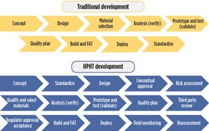
This legacy process stands in striking contrast with the HPHT development sequence, which contains significantly more steps, including:
- Regulatory approval of the concept.
- Formal risk assessment.
- Formal materials qualification.
- Third-party review, and regulator pre-approval.
- Field load monitoring and reassessment.
However, one of the biggest changes with the HPHT development process is determining where the standardization step is applied. In traditional developments, standardization comes at the end, after a long period of successful equipment use. In HPHT, it’s happening almost at the beginning for many equipment types, including BOPs. In many cases, standards have already been drafted or released prior to actual equipment deployment. While necessary from a risk management standpoint, the acceleration of standards development without the benefit of historical experience has proved to be a challenge to designers attempting to implement the new requirements, analogous to “flying an airplane while it’s being built.”
HPHT LANDSCAPE
The HPHT stakeholder landscape is difficult to navigate because of shifting requirements, roles and responsibilities. Additionally, miscommunication and/or misunderstanding between two or more parties can cause friction between individuals and companies. In general, the major factions include:
Regulator. The overarching regulation, 30 CFR 250.804, is the basis for U.S. governmental oversight and is where the HPHT delineation is codified. The regulators also oversee the conceptual deepwater operations plan and final DWOP process, by which documentation is submitted for acceptance or approval.
Industry. Historically the industry has been responsible for writing standards to track and comply with the regulation, such as the old 1PER15K and its successor, API 17TR8, now in its second edition. These guidelines are making their way into equipment-specific standards.
Operator. The operating companies need to drill and develop specific HPHT fields where they are invested. To do that, they require qualified equipment and need to fully characterize the operating conditions of the field and create functional specifications on this basis. As the stakeholder, they are also responsible for submitting the final qualification reports to the regulator.
Original equipment manufacturer (OEM). The OEM’s function consists of creating technical specifications for the equipment, and then designing and building the required prototypes. The manufacturers then perform the verification, validation and associated reporting necessary to demonstrate that all requirements have been met before building production hardware.
Independent third party. The I3P plays a unique role in the HPHT process, similar to a class society or certified verification authority. Their job is to perform due diligence by reviewing the OEM’s documents and operator specifications. Next, they prepare and resolve findings, then prepare the final qualification reports that are submitted to the regulator by the operator.
QUALIFICATION TEAM
To navigate the difficult HPHT development landscape, several companies have joined forces to form a qualification team. The goal is to qualify and approve all new equipment necessary to build a 20,000-psi subsea BOP stack for Gulf of Mexico deployment.
The Bureau of Safety and Environmental Enforcement’s (BSEE) 250.804 HPHT regulations were combined with the recently updated BOP regulations, including the new Subpart G implemented with the well control rule in 2016. Because of the evolving regulatory climate, the qualification team wanted to engage early and often with BSEE. This engagement has proved beneficial to all concerned parties.
The industry is represented by the American Petroleum Institute (API). API has been instrumental in facilitating BOP standards development, and the qualification team built on the work started by the API 17TR8 committee, drafting new HPHT qualification guidance specifically for BOPs. This guidance is being implemented as an Annex to API Specification 16A, 4th Edition. It is currently in draft form but is in final ballot and should be published within the next few months as an addendum to API 16A.
Stress Engineering Services is providing technical advisory services on behalf of an operator. From the operator’s perspective, BOP operations were analyzed in drilling, completions and intervention phases to create functional specifications with site-specific loads. Stress also is providing technical guidance and review of the work being done by the OEM, Baker Hughes, a GE company (BHGE).
BHGE’s legacy Hydril division produced some of the early 20,000-psi BOP prototypes and have been steadily progressing their development through the changing HPHT landscape. BHGE maintained their existing developments and drafted new technical specifications, but also implemented a new materials qualification plan. This included incorporating the new API guidance in their verification and validation procedures.
Finally, the independent third-party review is being provided by ABS, whose experience in performing class certification for BOPs has been beneficial to the project. ABS’s deliverable is a series of BOP qualification reports for BSEE review. ABS also is serving as liaison between all five parties, which has significantly enhanced communication. Although the company’s role is to review documentation as strictly an I3P, the qualification team expects that some of their work will translate directly into a class review of the stack.
HPHT BOP STACK
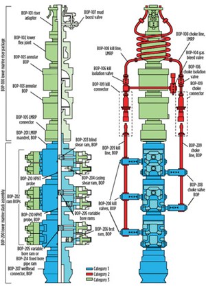
With the background overview process clearly defined, we can now focus on the details surrounding the equipment qualification progress of the 20,000-psi BOP stack, Fig. 2. The new BOP looks similar to the 15,000-psi version by design. BHGE has put a significant amount of effort into reducing the stack’s height and weight, so it can be handled and deployed by many of today’s existing rigs. Some of the earlier concepts were much larger and mandated a new, purpose-built rig to handle the 20,000-psi stack.
The configuration of the 20,000-psi BOP is conventional, too. Starting at the top, there is a riser adapter, flex joint, dual annular BOPs, and an LMRP connector. Many of these components are either identical to, or only slight modifications of, the conventional equipment on a 15,000-psi stack.
The new 20,000-psi equipment mostly resides in the lower portion, and consists of the LMRP mandrel, dual-body ram BOPs, and the wellhead connector. The BOP rams consist of a blind shear ram, casing shear ram, Hydril variable rams, and a test ram. The engineering team also is qualifying a 9 5/8-in. fixed pipe ram for use in completions and interventions. The choke and kill equipment is also new and 20,000-psi rated, consisting of dual block valves, isolation valves, a gas bleed valve, and piping and flex loops.
Qualifying subsystems. The scope of the current project is to qualify only the subsystems necessary to build a 20,000-psi BOP, not to actually construct the full stack. Fortunately, this allows the consortium to limit the development scope to manageable pieces. Specifically, the focus for the 20,000-psi equipment qualification is the subsystems shown in blue and red, Fig. 2.
Much of the discussion around HPHT has centered around categorizing equipment according to criticality, with Category 1 being the most critical and Category 3 being the least. In the case of the BOP, the team has identified the lower stack main drill-through tooling as Category 1 primary barrier equipment, or the “barrier-of-last-resort” in a well control scenario. This includes the ram BOPs, wellhead connector, shear rams, pipe rams, and C&K valves.
Category 2 is defined as secondary barrier equipment. It is rated to 20,000 psi and used for well control. On the BOP, it is the C&K lines, connectors, gas bleed valve, and isolation valves. The qualification team has defined Category 3 as either non-HPHT, or support equipment that does not comprise a critical barrier. This includes the LMRP drill-through equipment and BOP controls. The use of previously qualified, 15,000-psi or lower-rated equipment is acceptable for these functions.
The qualification team has defined the end game goal as follows: Once BSEE acceptance is obtained, the 20,000-psi BOP stack may be manufactured for field application. Separate approval will be required on a specific project basis. The distinction between acceptance and approval is that approval is site-specific, while acceptance is generically applied to equipment.
FUNCTIONAL/TECHNICAL SPECIFICATIONS
In this section, we will review specific steps in the qualification process. The first is to define the equipment’s operational loads and target ratings as a set of specifications. In this instance, our industry has adopted the approach set forth in the ASME code boiler and pressure vessel code. The ASME requires the end-user to prepare a design specification (UDS), defining all site-specific loads and operating conditions. These details are provided to the manufacturer, who designs and builds the equipment and prepares a manufacturer’s design report (MDR), documenting how the user’s requirements have been met or exceeded.
BSEE and API have adopted a similar process. However, in the drilling tool qualification scenario, the UDS is called a “functional specification” and is usually written by the operator, but it could be authored by a drilling contractor. The MDR is replaced by a “technical specification” written by the OEM.
The main difference between the two approaches is with how the equipment is certified. In the pressure vessel code, certification is performed by registered professional engineers from both parties—end-user and manufacturer. In the BSEE and industry process, certification is replaced by an I3P analysis where relevant documents and activity are reviewed, and summary reports are prepared for BSEE approval or acceptance.
HPHT materials selection. Once the specifications have been written, the real qualification work can begin. One of the new steps in the HPHT process has been an emphasis on materials qualification and selection. There are two motivations behind this new philosophy.
The first is to characterize the effect of the environment on materials as they operate at higher pressures and temperatures. The term, “environment,” primarily refers to the fluid and chemical combination of seawater, cathodic protection, mud, completion brines, and the sour environment due to produced fluids with hydrogen sulfide.
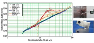
The second is to obtain new material properties to support a fracture mechanics fatigue analysis, Fig. 3. A fracture mechanics analysis is now required for certain critical HPHT BOP components per the new API 16A HPHT Annex draft. They can produce favorable fatigue lives relative to other methods in certain situations; however, the required material properties are poorly documented. The material test program will fill in the gaps, to enable an accurate analysis.
Testing is being performed on metallic and non-metallic materials. In the qualification stage, the test coupons are taken from sacrificial forgings or parts. In production, there will be limited testing via first-article inspection, prolongations, and other methods.
Ultimately the results will be used to justify the inputs for verification. This is a long, expensive endeavor, but it should create a solid foundation of materials information on which to build our industry’s future equipment.
VERIFICATION OF BOP EQUIPMENT
The next step is verification of the BOP equipment designs. The process employed by the engineering team is drawn from the new API 16A HPHT Annex draft, which is based on the the Boiler and Pressure Vessel Code. It also mirrors the approach defined in API 17TR8, with some key differences.
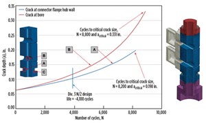
Verification involves several steps, and the process is laid out as a series of analytical checks against known failure modes, Fig. 4. These include plastic collapse, which is equivalent to burst or rupture; local failure, in which strains exceed certain limits and initiate cracks; ratcheting, which is failure due to progressive deformation, bolting failures, and fatigue. Fatigue analysis may be via the fracture mechanics approach, or more traditional S-N methods. In either case, environmental material properties are required as inputs.
Analytical verification provides a robust check against many failures, but it has limitations. A good example is sealing. There are serviceability and sealing checks that may be employed analytically, but the only way to know for sure that equipment will seal properly is to test it.
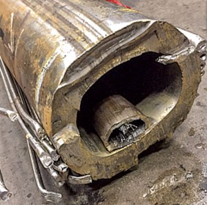
BOP validation process. Validation is the physical testing of prototypes, which are equivalent to the production equipment, to demonstrate compliance to specification requirements. The testing baseline is outlined in the recently updated API Specification 16A, in which validation testing requirements were revamped significantly, with the PR2 suite being the most robust. Additional validation requirements also have been imposed in the API 16A HPHT Annex draft. The validation program includes extensive thermal and cycling fatigue qualification for ram BOPs, as well as full-scale external load testing of the wellhead connector and 18-20 flange. The concept of operating, extreme and survival load ratings is also introduced, and carried into the HPHT standards in both API 16A and 17TR8. Finally, the protocol includes a robust shear test program, designed to comply with all aspects of the current Code of Federal Regulations, including the 2016 well control rule, Fig. 5.
INDEPENDENT THIRD-PARTY REVIEW
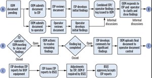
The I3P review process sets the stage for the actual project deliverables and justifies why the equipment is fit-for-service. After discussing requirements with all parties, the coalition developed a comprehensive review process, outlined in Fig. 6.
A prominent feature is that the initial review of each OEM document is done in parallel, by the I3P and the operator. These reviews are performed independently, but then comments are collected and resolved together. This is performed in three stages, consisting of informal close-out of minor comments, a formal findings review to resolve major comments, and then a document revision to implement major comment actions. The document is then released, and the associated findings and resolutions captured.
Independent third-party reports. When all qualification documents in a particular category have been reviewed and released, the I3P prepares a summary report for that category to document the work. The reports are laid out as seven “volumes” as follows:
- Report 1A is the basis of design, consisting of the technical specification, and also the risk assessment (usually a FMECA).
- Report 1B documents the materials selection and qualification, including the environmental testing reports.
- Report 1C summarizes the verification analysis, including the strength and fatigue analysis per the code requirements.
- Report 1D captures the validation testing performed on all the equipment, including 16A PR2, the HPHT Annex tests, and shearing tests.
- Report 1E documents the plan for actual field monitoring of loads. It is intended primarily to address fatigue loading and reassessment against the original assumptions made in the fatigue analysis.
- Report 1F involves the quality plan and handover of the qualification basis to production via materials specifications, inspections, and process routers, as captured in the inspection and test plan.
- Finally, Report 1G ties all the other reports together with the operator functional specification to assess fitness for service. While 1A through 1F apply to the equipment specifically, 1G applies to the equipment deployed in a particular operator’s field. Acceptance requires 1A through 1F, but 1G is required for approval.
These documents formally declare that the equipment is qualified and fit for service. The summary reports are submitted by the I3P, via the operator, for BSEE approval or acceptance.
QUALIFICATION STATUS
The process described above has been ongoing for several years, but the consortium is presently moving forward with the qualification of actual BOP equipment. BHGE is making steady progress in each 20,000-psi equipment subsystem, despite the evolving process and continually shifting standards and regulations. It has been challenging, but the engineering team has made significant strides toward the finish line by working together and maintaining strong communication.
At the current pace, it is expected that the OEM work will complete around the end of 2019, with the I3P and regulatory reviews following afterward. The team hopes to attain final acceptance sometime around mid-2020. ![]()

