Applying ultra-deep LWD resistivity technology successfully in a SAGD operation
Operators develop oil sand reservoirs, mostly using the steam-assisted gravity drainage (SAGD) technique, which requires drilling two parallel wells, one above the other, and separated by a fixed distance. The upper well injects heated steam to increase oil mobility for production in the lower well, making this method of extraction costly.
To effectively produce such reservoirs and reduce well costs, optimized well placement in the bitumen body is extremely important. Placing the producer well close to the reservoir basement is preferred to maximize production, but uncertainty in the position of the basement can make this difficult. A new ultra-deep logging-while-drilling (LWD) resistivity service helps to map the reservoir top and base for optimal well placement and completion.
The EarthStar is a new ultra-deep resistivity service that offers a fresh perspective on geosteering in challenging environments, illuminating and mapping the reservoir structure around the wellbore on a scale not attainable with conventional LWD tools. The service uses a tilted antenna design that makes the tool directionally sensitive. Complex geology can be mapped accurately ten times farther from the wellbore than is possible with conventional LWD azimuthal tools.
The ultra-deep resistivity service provides estimates of the distance, direction, and orientation of geological boundaries, relative to the wellbore and the resistivity of the formations adjacent to those boundaries. The system can detect boundaries up to 200 ft (60 m) from the wellbore, in the right conditions. This information allows mapping of the bitumen body for optimal placement of the well pairs, to maximize reservoir drainage and increase production in SAGD operations.
INTRODUCTION
For heavy oil and bitumen reservoirs, multiple techniques are used to reduce viscosity and help improve mobility of heavy oil to achieve higher production and recovery. SAGD is the most widely used technique to enhance recovery of heavy crude oil and bitumen. For a SAGD operation, operators typically drill a parallel pair of horizontal wells in the reservoir, with a vertical separation of approximately 15 to 30 ft (5 to 10 m). The injected steam from the upper well creates a steam chamber at the top of the reservoir and releases the heat into the heavy oil to reduce its viscosity. The heated oil then drains by gravity into the lower producer well.
Maximizing production from SAGD projects requires a good understanding of the geological structures and properties of the reservoir, to enable optimal well placement. Conventional LWD azimuthal tools facilitate geosteering and well placement in the reservoir, but with a limited detection range. Simultaneously mapping the top and base of the reservoir is problematic with such technology because of the limited detection range, resulting in suboptimal well placement.
The EarthStar ultra-deep LWD resistivity service detects boundaries up to 200 ft (61 m) from the wellbore, with multi-layer bed-boundary-detection capabilities, allowing full delineation of the reservoir top and base, and the structure of the bitumen layers. The service provides multiple azimuthal measurements that greatly enhance geosteering and provide significantly greater control over well placement. With such capabilities, operators can improve real-time geosteering decisions and proactively adjust the wellbore placement for improved reservoir drainage in SAGD applications.
TOOL DESIGN AND CONFIGURATION
The ultra-deep resistivity tool consists of a transmitter sub and multiple receiver subs (Fig. 1). The transmitter sub contains two transmitters—a tilted antenna and a coaxial antenna operating at frequencies from 1 to 64 kHz. Each receiver sub is equipped with three tilted receiver antennas, with different azimuthal orientations relative to the high side of the bottomhole assembly (BHA).
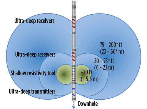
The separation between the receivers and transmitter is variable, providing detection ranges from 20 to 200 ft (6 to 61 m). Generally speaking, the larger the separation between the transmitter and receiver, the deeper the detection capability. Figure 1 shows one possible configuration, with one receiver achieving a detection range of between 20 and 75 ft (6 to 23 m), and the second receiver achieving a detection range of more than 200 ft (61 m). Detection range is a function of formation resistivity, the separation between transmitter and receiver, and the operating frequency. Pre-well modeling helps to determine the optimal receiver placement, relative to the transmitter, for a given target detection range.
Measurements from all the receivers at multiple frequencies provide input to an inversion, which determines the position and resistivity of multiple beds around the wellbore. In addition, azimuthal geosignal and azimuthal resistivity measurements are available from the same receivers, providing resistivity images around the wellbore.
FIELD RESULT FOR A SAGD APPLICATION
The ultra-deep resistivity service demonstrated its ability to identify fundamental reservoir characteristics in a Canadian heavy oil field. The positions of the reservoir top and base, and internal structures related to reservoir quality, were among the characteristics of concern. Understanding the bitumen quality of zones within the reservoir guided the steaming strategy for the well, potentially toward a lower steam-oil ratio (SOR) (the amount of steam injected compared to bitumen produced), a common metric used to evaluate the success of a well.
With thousands of barrels of water injected as steam each day, delineation of heated and water-flooded zones within the reservoir is important for more effective placement of second-stage infill production wells, further reducing a project’s SOR. The ultra-deep resistivity service can map the lower resistivity associated with water and heat, along with the cap rock, basement, water zones, and low-saturation zones. The service provides a means of determining large-scale reservoir features that was not available previously.
Figure 2 shows an example of a field operation in a SAGD environment. The main objective of the geosteering operation was to place an injector wellbore (solid line) above a producer well (dashed line). A secondary objective was to map the top and bottom boundaries of the high-resistivity reservoir within a true vertical depth (TVD) range from X480 to X505 m. The mapping of geological structures in such a complex reservoir is extremely important for understanding formation profiles, and it can play a vital role when evaluating the extent of the steam saturation and propagation.
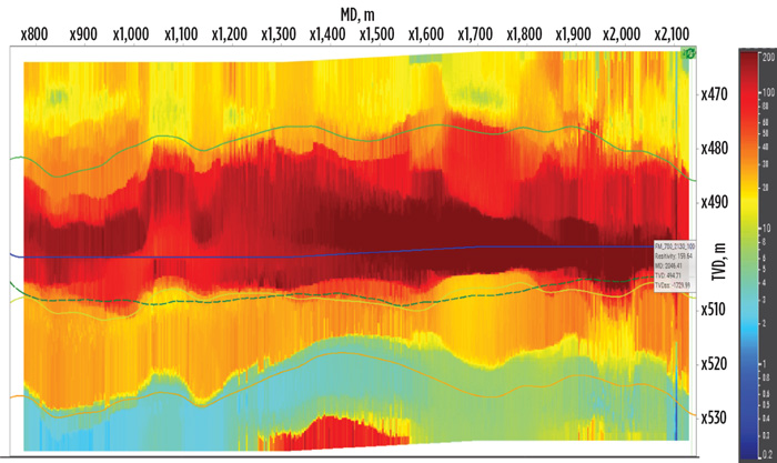
For such high-resistivity, multi-layered formations, higher-frequency measurements differentiate layered boundaries most effectively. The operating frequency ranged from 8 to 32 kHz for this field run. A pre-well model, based on logs from nearby wells, helped to predict the tool performance and select the desired operating frequency and transmitter-to-receiver spacing. The ultra-deep resistivity service provides two methods for visualizing the reservoir: an inversion result, illustrating the vertical resistivity profile above and below the well; and a set of azimuthal geosignal and resistivity measurements, providing a 360°view around the wellbore. Figure 3 shows both methods.
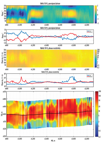
In Fig. 3, the top track shows the azimuthal phase geosignal image from the 8-kHz firing at a 50-ft (15-m) transmitter-receiver spacing. The second track shows upward- and downward-facing geosignal curves from the same firing. The third track shows the azimuthal phase resistivity image from the 16-kHz firing at a 19-ft (6-m) spacing, while the fourth track shows the corresponding upward and downward-facing curves. The bottom plot shows the inversion result. The combination of ultra-deep azimuthal geosignals and resistivities with a vertical inversion result helps the operator to steer the well in three dimensions.
CONCLUSIONS
A SAGD operator used the new ultra-deep LWD resistivity technology in a complex, high-resistivity structure, to successfully place the well accurately, and map the top and base of the reservoir. A pre-well model, based on nearby offset logs, helped to establish the optimal transmitter-to-receiver spacing and operating frequency. Real-time measurements from the tool confirmed the geological structures and formation properties, and guided geosteering decisions.
The field results validated the pre-well modeling accuracy and performance of the system in SAGD formations. The EarthStar ultra-deep resistivity service achieved the necessary objectives of geosteering the well and mapping the reservoir, delineating the top, base, and main structural features of the SAGD reservoir. WO
- SBM executive sees strong FPSO market on back of deepwater trend (April)
- Unlocking ultra-high-pressure reserves: Why Shenandoah is a milestone for deepwater engineering and advanced chemistry (March)
- FPSOs, reliability and gas turbine air intake filtration (February)
- Oil and gas in the capitals: Norway sustains the industry (December 2025)
- Overcoming extreme challenges: Advanced chemical solutions for offshore oil production integrity (September 2025)
- Powering Mero-3: A look inside one of the world’s largest deepwater FPSOs (August 2025)
- Subsea technology- Corrosion monitoring: From failure to success (February 2024)
- Adoption of wireless intelligent completions advances (May 2019)
- Majors double down as takeaway crunch eases (April 2019)
- What’s new in well logging and formation evaluation (April 2019)
- Qualification of a 20,000-psi subsea BOP: A collaborative approach (February 2019)
- ConocoPhillips’ Greg Leveille sees rapid trajectory of technical advancement continuing (February 2019)

