Three-dimensional mapping improves reservoir understanding with volumetric and 3D insights
As reservoir complexity increases, drillers require expanded reservoir mapping capabilities with the ability to map resistive boundaries on or near the vertical axis. Conventional 2D reservoir mapping does not allow for lateral changes in the plane, and the 1D inversion algorithm only inverts for resistivity profile vertically at each given point on the trajectory.
An improved understanding of the reservoir structure and fluid contact in a full 3D context around the wellbore enables geoscientists to better steer the well. Recent advancements in deep directional electromagnetic (EM) measurements, for mapping deeper into the reservoir, have enabled looking ahead of the bit while drilling, reducing risk associated with unplanned penetration of certain formations.

The GeoSphere 360* 3D reservoir mapping-while-drilling service from Schlumberger includes three parts: a set of new measurements acquired downhole and transmitted to surface in real time; a new inversion algorithm that is model-independent and fit for any reservoir complexity; and a new cloud computing capability that enables answers in real time while drilling, Fig. 1. Compared with previously acquired well logs, the new set of measurements almost doubles in number. Because the new inversion algorithm is not confined to any specific forms of models, it is suitable for exploring complex reservoir settings and finding solutions.
The latest advances in the scalability and algorithm design of the cloud computing infrastructure improve turnaround time for the new inversion by more than 100 times. When combined, the features provide a 3D reservoir map without having to compromise between high resolution and depth of investigation. The real-time 3D reservoir map enables an up-to-date reservoir model that helps the operator make informed decisions while drilling and enabling targeting of more complex reservoirs and improving geosteering results. The ability to update reservoir models can help improve drilling, completion, production and reservoir management.
How the technology works. The 3D reservoir mapping-while-drilling service acquires 360° EM tensor data of the formation surrounding the tool, using tilted magnetic dipole antennas within azimuthal resistivity. It sends the data uphole in real time via mud pulse telemetry or wired drill pipe. The modular tool layout has one transmitter and multiple receivers spaced between 5 m and 35 m apart. Antennas operate at multiple frequencies between 2 kHz and 96 kHz.
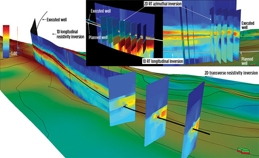
Using cloud computing, the 3D reservoir mapping-while-drilling technology inverts the large datasets with a 2D azimuthal pixel-based algorithm. The service then produces 3D-resistivity volumes, which are filtered to understand the geometrical relationship of the resistive geobodies around the wellbore, calibrating the seismic data and feeding into reservoir modeling workflows. The 2D inversions integrate the 1D inversion results, illustrating vertical separations between two resistive bodies in a lateral plane, Fig. 2. The 2D transverse inversion slices illustrate the lateral variation in the resistive bodies. The 2D transverse inversion enhances integration of the geological dataset from a nearby wellbore to reservoir scale, enabling highly educated geosteering decisions at realistic drilling ROPs.
Because the full 3D data have significantly more data points, the pre-drill seismic images and geobody extractions are calibrated more accurately than what is possible with conventional technology. Comparing all data sources enables further validation of interpretation. Additionally, subsurface geomodels, updated in real time to a high resolution, enable higher-confidence strategic geosteering decisions in 3D.
Inversion algorithm. Eight measurement classes, combined with shallow conventional resistivity data, are inverted in real time using cloud computing for the 2D transverse resistivity inversion. The resistivity and anisotropy of each pixel in a symmetric grid are inverted with the two alignment angles of the trajectory w.r.t. the 2D plane. A single data point or a data window can be used in the inversion to estimate the resistivity anisotropy inside the 2D plane and its alignment angles. With the single data point and execution of the inversion on cloud computing services, a turnaround time of 15 min. or less can be achieved for a two-receiver BHA, enabling real-time inversion processing of the measurements transmitted uphole. A 3D reservoir map can be derived from the multiple 2D inversions.
Data transmission. The 3D reservoir mapping-while-drilling service generates numerous real-time measurements. Conventional 2D reservoir mapping technology generates a multi-frequency measurement set with 55 measurements, transmitting 30 curves from three frequencies in real time. Compared with the previous technology, the number of curves in each measurement set using the 3D reservoir mapping technology almost doubles. Every measurement set from one transmitter-receiver pair has 96 measurements, which means a total of 54 curves are sent in real time.
Advanced compression algorithms can achieve an effective rate of more than 80 bits per second (bps) in the latest MWD system. This enables transmission of the large number of curves needed for 3D reservoir mapping technology in real time, using a mud-pulse telemetry system.
CASE STUDIES
Operators in the North Sea and Australia have used the 3D mapping-while-drilling technology to improve reservoir understanding.
North Sea operator extends well and gains extra net pay interval. In a well with a coarsening upward sequence of offshore shales and lower shoreface sediments, an operator wanted to land as early as possible, to ensure maximum net sand once inside the reservoir. Another objective was to stay high on the structure, maintaining between 3 m and 7 m, TVD, from the top.
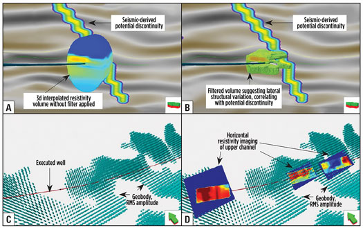
Because of a wedge geometry and predicted volume from seismic data, the ability to map the structural variations of the reservoir laterally and vertically would be a significant advantage, Fig. 3. The operator also wanted to optimize high-angle well placement for total hydrocarbon recovery and deployed geosteering support for both the landing and the reservoir section. A conventional reservoir mapping-while-drilling service provided 1D formation resistivity mapping while drilling, but real-time interpretation was limited by this type of inversion. More advanced 2D transverse inversions provide new information, highlighting 3D structural complexity and fluid movements locally in the near-wellbore region.
The application of the 3D mapping-while-drilling service enabled steering away from the planned trajectory toward the sweet spot, which was located sideways from the planned trajectory. This was made possible by the real-time processing of the 2D transverse resistivity inversions while drilling from the heel up to the total depth of the 8.5-in. horizontal section. 2D advanced transverse inversions were incorporated into the current geosteering workflow. This provided a complete 3D structural understanding from the landing zone when approaching the reservoir top, all the way to steering inside the main section in the horizontal interval. This integrated approach was used for 3D reservoir mapping while drilling and provided relevant real-time information to steer laterally, to keep the borehole within the optimal reservoir exposure.
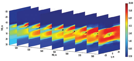
The 2D transverse inversions while drilling mapped a higher resistive geobody located sideways from the wellbore path. From the inversion results, it also was possible to identify a lateral dip where inclination and direction correlated with the structural true dips derived from the borehole LWD density images. This novel real-time information supported a strategic change in the trajectory to turn fully westward, respecting the dogleg severity limit for running a production liner to target and intercept the sweet spot. This azimuthal 3D reservoir steering decision delivered nearly 100 m, MD, of extra net pay interval by extending the well inside this reservoir section.
North Sea operator maximizes reservoir exposure. To enable strategic geosteering decisions, another operator in the North Sea wanted to integrate data from multiple scales of measurement, such as borehole-scale and borehole-derived near–seismic-scaled LWD, with attribute analysis of surface seismic, Fig. 4. The well contained significant static and dynamic uncertainties throughout the well design and execution phases, including fluid distribution and structural geometry.
The project’s objective was to improve and enhance geosteering operations in a complex reservoir, which contains an oil accumulation with a gas cap. The reservoir comprised sandstones of a deepwater turbidite channel system. The geological structure was a complex, four-way dip closer anticline with bounding faults and expected sub-seismic faulting, increasing the level of uncertainty and complexity. An area of bypassed oil identified on the eastern flank of the structure was the target for an infill well.
Australian operator geosteers well 100% inside target zone. In an oil field offshore Australia, an operator wanted to drill a new producer well that could be geosteered to maximize reservoir exposure while maintaining DLS and well tortuosity, thus ensuring a smooth completion run. The ability to map the reservoir and know where to blank it off was critical for success. The operator also wanted to blank off conglomerate and avoid a channel cut to the reservoir layer.
Other common challenges included structural complexity, faults, channel cuts, reservoir property lateral variations, and oil/water contact (OWC).
The operator selected the 3D reservoir mapping-while-drilling service to use the resistivity profile map from the conventional curtain section inversion result to map the top and base of the reservoir and assist geosteering to optimize the well position vertically. Toward the toe of the well, the service could potentially help geosteering azimuthally. The service can map the resistivity profile longitudinally and to the left and right, with the depth of detection covering the previous well. This could help increase understanding of the reservoir and the previous well’s issue. Furthermore, it would help to map the water saturation profile, if OWC moved up in some areas due to existing well production.
The service enabled the operator to achieve all objectives. The well was geosteered 100% inside the target zone and reached the required length. Real-time 3D reservoir mapping enabled the operator to make informed decisions on the well path in the completion design. The service also mapped some conductive features, helping the operator better understand the reservoir dynamics related to fluid movement in the field. For the first time, the operator ran 12-bps mud-pulse telemetry without issues. Despite the additional data required to send uphole and the high ROP of more than 30 m/hr, the update rate was very good at 1.5 m for both receivers. During post-job, a 3D pointset and 3D cube delivered to the operator enabled better visualization and utilization of data for reservoir model refining.
VALUE DELIVERED
The ability to achieve 3D reservoir mapping while drilling provides a better understanding of the 3D geological environment and fluid distribution with a deep depth of investigation, as well as the required information to create support for reservoir steering decisions for optimal well positioning. By improving reservoir understanding, operators can book more reserves, unlock more oil production, enhance completion and production design, place fewer wells with greater certainty and improve returns from complex reservoirs. The 3D reservoir mapping-while-drilling service capabilities open opportunities for additional applications and integration with 3D or 4D seismic workflows.


- Shifting from calendar to usage-based maintenance: Proven results that demand your attention (June)
- Executive viewpoint: Methane monitoring goes digital (May)
- Drilling technology: Optimizing high-pressure pump performance with fluid end advances (May)
- John Henry vs the steam drill: Will the robots win? (May)
- Why oil and gas companies should invest in ruggedized edge computing (May)
- Drilling technology: Drill bit advances continue their relentless march forward (March)
- Subsea technology- Corrosion monitoring: From failure to success (February 2024)
- Applying ultra-deep LWD resistivity technology successfully in a SAGD operation (May 2019)
- Adoption of wireless intelligent completions advances (May 2019)
- Majors double down as takeaway crunch eases (April 2019)
- What’s new in well logging and formation evaluation (April 2019)
- Qualification of a 20,000-psi subsea BOP: A collaborative approach (February 2019)

