Making in-situ flowmeter calibration a reality
Accurately measuring the mixture of oil, water and gas in field conditions is a major challenge for the industry. Multiphase flowmeters (MFMs) have opened the door to the development of marginal assets and promote more efficient exploitation of larger fields. A multiphase meter can eliminate the need for a test separator, which is large and difficult to maintain, leading to possible smaller platforms.
Existing facilities also can be upgraded to take subsea tie-backs without having to add an extra test separator. Indeed, an existing test separator may be reused as an additional production separator to cope with extra production. MFMs also give continuous measurements, allowing better reservoir management, well optimization and a quick response to water break-through and similar events. Also, having a subsea multiphase meter on each wellhead facilitates the production and flow assurance issues, and a better reservoir recovery factor.
The ability to provide real-time flow measurement will lead to a greater uptake in MFMs worldwide. However, due to the costs required to send them back to facilities for calibration, the challenges of validating them in-situ throughout their time in service must be addressed. This is becoming an even more significant issue, as the industry continues to exploit deeper and more remote fields, Fig. 1. Additionally, accurate flow measurement near the wellhead enables users to make informed decisions about critical operational procedures, such as optimization, obtaining reservoir characteristics, enhanced recovery techniques and the mitigation of pipeline flow assurance challenges.

IDENTIFYING CHALLENGES
However, despite the potential benefits, the use of multiphase flowmeters in oil and gas applications, particularly when installed for remote or subsea application, is fraught with challenges. While ensuring the ongoing performance of multiphase flowmeters is critical to avoid the financial exposure and risks associated with their mismeasurement, so far little has been done to address the challenges associated with their ongoing verification or calibration in-situ, for both topside and subsea installations. Furthermore, there is confusion between validating a MFM’s performance before using it in the field and establishing the true performance of the MFM in a controlled environment (i.e. facilities dedicated to producing multiphase flow).
All flowmetering devices monitoring oil and gas flows provide information at the in-situ conditions (i.e. at line pressure and temperature). Meanwhile, the volumetric flowrate of water, oil and gas needs to be estimated at standard conditions because of the business requirement that any fluid must be sold at stabilized conditions, which is referred to as “standard conditions.”
To accurately convert meter readings from in-situ to report flowrates at standard conditions requires knowledge of fluid properties, or pressure-volume-temperature (PVT) following pressure and temperature change, irrespective of the type of meter or technology used. If a provider of MFMs claims there is no PVT required, there is a lack of understanding about the live fluid, which is used in field conditions.
Additionally, MFMs are particularly affected by the use of the PVT information for two main reasons. They can be working at extremely high pressure and temperature, which requires a significant correction to convert the measured flowrates to standard conditions. For example, a flowmeter may be calibrated with fluid at 20°C (68°F), and atmospheric conditions, but the fluid temperature in-situ could actually be as great as 100°C (212°F) and > 50 bar(a) (725 psi(a)). This will have a significant effect on flow measurement accuracy if not properly accounted for. Also, because no separation is made between the different flow phases, a large amount of gas can be dissolved inside the oil, or some of the condensates could be in gas phases at meter conditions when liquid at standard conditions.
An uncertainty budget for the flowmeter when in use must, therefore, be constructed, taking account of additional uncertainties arising from interpolation and extrapolation from calibration conditions. Developing realistic uncertainty budgets for complex measurement processes is not trivial, requiring much more than just the calibration certificates for the individual components. Calculations for an uncertainty budget must, therefore, capture all the sources of uncertainty.
TRACEABILITY
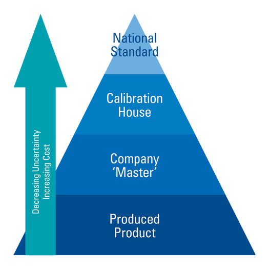
Traceability is the process of proving the performance of equipment for each stage of calibration. To provide the highest quality of measurement and, therefore, the lowest uncertainty budget, flowmeters should be traceable to primary standards, which are calibrated against National Measurement Standards. This, therefore, involves being able to trace your calibrated device to its reference or process, which, in turn, can be tracked to its calibration source, and so on, all the way to a national standard. This is often regarded as a “chain” or “pyramid” of traceability, Fig. 2. Note that the accuracy is improving as you rise through each level in the pyramid until the pinnacle is reached. Manufacturers sometimes overlook this process.
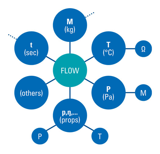
For a derived quantity, such as oil volumetric flowrate measured by a flowmeter on a production platform, traceability can be complex. This is because a number of measurements are now required: mass, time, temperature, pressure, fluid properties and others, Fig. 3. Each of these quantities needs its own calibration pedigree, so full traceability of a flowmeter calibration essentially requires an extended family of pyramids. The facility should be also be ISO 17 025-compliant to ensure the quality in the process of calibrating or certifying equipment.
PERFORMANCE MAPPING
It is important to have proper mapping of the performance/uncertainty of an MFM, and this is based on the expected profile of oil and gas production. However, end-users face a substantial challenge when trying to select and review accurate meter performance, because MFM manufacturers use the set of output parameters to state the performance of their products with the most attractive uncertainty or generic information.
Our research has shown that stated meter performance levels are, in general, overly optimistic. In addition, manufacturers oftentimes do not provide the end-user with the expected output specification of oil, water and gas flowrates. Instead, they provide a combination of different parameters at line conditions, because they do not have the expertise in fluid properties to translate to standard conditions. This is a very generic approach, even for a common single-phase flowmeter type, such as Coriolis. This leaves the end-user to translate any numbers to the expected parameters and associated values themselves, if, indeed, the manufacturer has provided them with enough relevant data to achieve this. As this information is left to the manufacturers’ discretion, there are no standard requirements.
Numerous combinations of technologies exist on the market, none of which address the entire spectrum of parameters possible in multiphase or perform systematically better than the others. When the end-user has selected an MFM, the fluid behavior should also be taken into account, as this establishes the true performance at standard conditions. This step is especially important, because it will highlight the level of uncertainty that should be achieved in the different fluid properties faced in field conditions.
It should be remembered that it is the combination of the performance of the MFMs under well-established flow and process conditions, and the estimation of the uncertainty of the relevant PVT package, from line to standard conditions, that will provide the overall uncertainty of the system in field conditions. This does not have to be physically in the field to establish the overall uncertainty, for two reasons: (1) the uncertainty in field conditions is low, due to a lack of accurate reference measurement. Test separators are rarely better than ± 5%–10% following the conditions; this can be highlighted by the fact that the allocation factor is, in general, smaller than 1.00 and in the range of 0.85, and (2) the capability to do the test at a full range of conditions, versus gas volume fraction (GVF) and water-liquid ratio (WLR), is not possible most of the time. Therefore, the best option is a third-party laboratory, using the lowest possible uncertainty with a two-step analysis that uses (1) pure flowmeter performance; and (2) compatible equations of state with the associated uncertainty.
Tackling in-situ flowmeter performance. There are two methods that can be used to address this. The first is to take the manufacturer’s statement, literature, and the laboratory’s knowledge to establish the performance of the water, oil and gas at line conditions. This performance is usually established, based on some specific range of GVF and WLR and in line with the expected flow conditions for a given application. To ensure that performance estimates are correct, a unique analysis, based on the Monte Carlo simulation, is developed and the uncertainty established on the total mass flowrate and total volumetric flowrate. This essentially uses the performance information relating to the gas fraction, or GVF, and the data associated with the WLR. This is then used via a propagation of errors, based on the Monte Carlo simulation, to establish the uncertainty on the total mass flowrate and total volumetric flowrate. Then, based on the fact that most flowmeters are calibrated on the Venturi measurement, the performance for the liquid, gas, water and oil is established clearly. This also highlights the complete distribution and the possible skewness in the MPM performance versus the GVF and WLR.
This innovative algorithmic computation provides a unique understanding of the response of the MFMs, based on the small set of industry-available recorded data that has been recorded at calibration facilities to date. This performance analysis could then be coupled with the PVT uncertainty performance, using PVT software developed by the UK’s Designated Institute for Flow Measurement over the last 40 years. This substantial database of composition is unique, as it is based on physical and real measurements collected over time. This type of data accumulation is superior/opposite of many PVT simulators which aggregate the equations of state (EOS) with little consideration of the validity.
This is the benefit of a national flow measurement institute for developing a commercial solution for end-users and leading the development of industry standards. The third step is then to combine both uncertainties from the MFM performance and from the EOS, and propagate this to the standard conditions. There is no limitation in the type of fluid that could be simulated by this desk analysis. This allows us to establish, without any ambiguity, the performance and how the meter will behave in field conditions and delivers an extremely powerful detailed analysis of the MFM performance, not only on the metrology but also on a meter’s maintenance and operating cost, Fig. 4.
Wellsite analysis. The second MPM performance review method is at the wellsite (and ideally it should be an extension of the previous one), either by remote or physical witnessing. This is usually done if there is some doubt about the performance of the currently deployed MFM, so that secondary equipment is required to verify it, or when advice is required on the best metering solution to be defined as a reference. As indicated earlier, in field conditions, the uncertainty of any reference device is higher than what can be delivered in well-controlled conditions, such as in third-party facilities.
At this stage, it is not the real performance that we are reviewing, but the validity of the MFM performance. When this process is being conducted at TÜV SÜD National Engineering Laboratory, this includes identifying the best metering solution to be defined as a reference. An analysis of the flow regime or flow structure and type of mixing is made prior to the evaluation.
After meter selection, a test program is established, and a specific procedure defined to validate the response of the MFM, using engineering expertise and some statistical evaluation criteria. It is then possible to understand the typical response of the MFM in the specific field conditions, and identify the sweet spot and what should be avoided. This could result in a new manufacturer’s maintenance program, the MFM’s replacement, or the installation of a complementary device, depending on the end-user’s expectation.
The evaluation is made on the reliability of the current MFM in place against the reference meter. A specific statistical analysis is used to state the confidence level that could be demonstrated for different flow conditions (different mix of oil, water and gas, and/or pressure and temperature), following the choke opening or other interventions that can be made to upset the flow.
COST REDUCTION
Both methods described above, to address in-situ meter performance, can be used to develop a proper analysis and reduce the maintenance program by identifying the MFMs that really require maintenance. This can be seen as an extension of conditioned-based monitoring (CBM), which is being developed for use with single-phase meters, with a view to reducing calibration frequency. This can make a significant contribution to OPEX optimization by reducing the overall annual cost of an MFM.
Overall, the work to be done to state the uncertainty accurately, and therefore the performance of MFMs, requires expertise and precise calculations. Thorough mapping of MFM performance against its in-situ application should be established by either oil and gas operators, or third-party multiphase flowmeter experts, and validated when possible at a calibration facility. We would advise that this work should not be left solely to meter manufacturers, as they can be overly optimistic about their product performance.

- Tethered BOP technology enables DP rigs to drill in shallow water (June)
- What's new in production: Lighten up (June)
- Late-life field management: Repair, repurposing and obsolescence management support sustainable well integrity (June)
- Enhancing Lower Tertiary recovery and profitability: The options – Part 2 (May)
- A Baker Hughes executive assesses the electrification effort (May)
- Nova Scotia’s Premier aims to revive province’s oil and gas activity (May)
- Subsea technology- Corrosion monitoring: From failure to success (February 2024)
- Applying ultra-deep LWD resistivity technology successfully in a SAGD operation (May 2019)
- Adoption of wireless intelligent completions advances (May 2019)
- Majors double down as takeaway crunch eases (April 2019)
- What’s new in well logging and formation evaluation (April 2019)
- Qualification of a 20,000-psi subsea BOP: A collaborative approach (February 2019)

