Digital technology provides high-density tortuosity logging to address drilling, production challenges
When discussing digital technology in the energy industry, many terms come to mind—AI, big data and process automation. While such terminology has become ubiquitous, the role of digital in driving change in an industry that has traditionally been slow to react cannot be underestimated. One area of intriguing growth is in using technology to better understand what’s going on downhole. Many software applications and algorithms have been developed to reveal how downhole parameters influence drilling operations.
An underdiscussed area is in how high-density tortuosity logging helps identify optimal artificial lift equipment placement to extend the life of a well. In the past, logging solutions did not incorporate tortuosity logs, instead relying on measurement-while-drilling (MWD) surveys or interval gyro surveys with calipers to analyze wellbore geometry based off dogleg severity (DLS). Such surveys, while often of acceptable quality for specific applications, do not provide high-accuracy, high-resolution analysis of tortuosity and obstruction in the wellbore. To address this gap in the market, Gyrodata developed and patented a new high-density wellbore logging technology, MicroGuide. The insight available from this new technology offering represents a step-change in how cased-hole logging is approached in the modern oil field.
THEORY AND TECHNOLOGY
When planning how to drill a well, its predetermined path is generally thought of as a relatively smooth curve. Deviations from this trajectory are commonly referred to as tortuosity, determined by taking the ratio of the actual distance between two points, including any curves, and dividing it by the straight-line distance. When there are larger variations in wellbore path over shorter distances, a variety of problems occur, including setting and passing casings through the deviated portion(s), as well as installing and passing production equipment through the same portion(s). Both previous and current systems have largely sought to use the measured dogleg of the wellbore to provide information regarding the wellbore path, but such information is often difficult to use and lacks the detail or clarity necessary to truly optimize well placement.
The MicroGuide system is run downhole to receive data from a plurality of survey stations on the wellbore log. The data are obtained from gyroscopic tools, magnetic instruments, or a combination thereof. In addition, the system defines reference lines for the wellbore path, based on the received data, and determines displacements of the wellbore path from the reference lines. Through a series of calculations based on this incoming information, the wellbore shape can be visualized in 3D, as the physical system is run in hole and the data are sent to surface.
Having this information presented on a computer allows an operator to make critical decisions on well development and more effectively drill a low-tortuosity wellbore that is consistent with the predetermined plan. In the case of running the MicroGuide system after drilling the section, understanding wellbore tortuosity can help the operator make better decisions on placement for artificial lift and other equipment, in line with low areas of tortuosity. It would otherwise be impossible to make such informed decisions without the higher levels of detail and accuracy obtained using the system.
APPLICATIONS
Improving ESP placement to increase production, eliminate equipment damage. An operator in the Middle East had previously installed an electrical submersible pump (ESP) at 5,800-ft measured depth (MD) after drilling a sidetrack. While initial production from the ESP hovered near approximately 390 bopd for several days, it dropped down to 0 bopd shortly thereafter. Further investigation was necessary to determine the wellbore’s condition before initiating workover operations, as the operator suspected that the cause of poor production was insufficient submergence of the ESP. The pump’s original placement in a shallow location (between approximately 5,700 to 5,900 ft, MD) was selected, due to the high DLS (5o to 7° per 100 ft) of the 7-in. liner deeper in the well, as indicated by a conventional MWD survey.
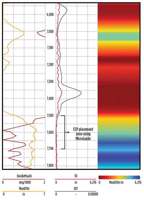
Gyrodata assessed the existing downhole data to determine an appropriate course of action. Based on the available information, the MicroGuide high-density tortuosity logging service was run to assess the wellbore and reveal a more accurate placement for the ESP. The tortuosity, maximum tool OD, and other well-related analytics were delivered to the operator, information that was not typically captured via conventional MWD DLS calculations. The MicroGuide technology indicated that it was possible to traverse the area of high tortuosity from 6,000 to 7,500 ft and place the ESP between 7,570 and 7,770 ft, the preferred depth for high-yield production, Fig. 1. After proceeding with the new placement, the operator continued to use the technology to ensure safe operations and avoid any damage to the ESP during conveyance.
After successfully installing the ESP at 7,650 ft, based on the logs, the pump began producing again, increasing from 390 bopd to 600 bopd. In addition to this almost 54% production increase, the operator achieved time and cost-savings by avoiding the start/stop ESP operations every three to four weeks, including workovers. By revealing the limitations of a conventional MWD placement, the MicroGuide service became a part of the operator’s future well planning, allowing them to properly place ESPs and avoid additional premature failures.
In Latin America, an operator was experiencing challenges with ESP failure and incurring significant costs from lost time and damaged equipment. After having difficulty running the casing string, the operator suspected that there were problems with the bottomhole assembly (BHA), but the well had been drilled according to plan and in line with readings from the MWD sensors. To determine the causes of equipment damage and failure, the operator decided to run the MicroGuide logging system in the 9⅝-in. casing section of the well.
The well was drilled initially with a rotary steerable system and surveyed with a drop gyro and MWD system, down to 2,705 m (8,875 ft). MWD surveys were only collected to TD at 3,272 m (10,750 ft). The MWD surveys on the last 400 m (1,312 ft) showed that with regard to azimuth, inclination was building from 58° to 70° over the section. However, there were indications of issues with the 12¼-in. BHA on the trip out of hole, making backreaming from 3,290 to 2,775 m (10,794 to 9,104 ft) and hole cleaning from 3,290 to 3,156 m (10,794 to 10,354 ft) necessary. When running the 9⅝-in. casing, the string got stuck at 3,264 m (10,709 ft) and could not be run further. Repeated attempts to pick up the string failed, with the operator having to perform a clean-out run to scrape the casing area clean. After running the completion assembly and placing the ESPs, production briefly came online before both ESPs failed.
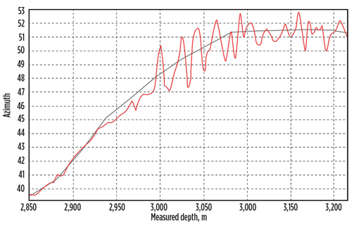
Running the MicroGuide system allowed the operator to track the well path at intervals of 1 ft, which showed a dramatically different picture of how the well had been drilled than what the operator previously had seen with just the MWD data, Fig. 2. While examination of the MWD sensor readings revealed no evidence of gross error, the well had not been drilled as expected, which was determined by the gyro survey. The operator already had incurred costs of more than $7 million from lost time and damaged equipment, but the MicroGuide system identified micro-doglegs in the casing not picked up by the MWD surveys, with data collected at stand-length intervals. The high-density wellbore data revealed the performance limitations of the existing BHA and helped the operator determine that optimal placement of the ESPs was 150 m (492 ft) higher in the wellbore, to avoid further damage.
Optimizing rod guide placement after detecting wellbore anomalies. An operator in the Anadarko basin near Canadian, Texas, had equipped a well with a rod-pump artificial lift system to improve production. After just one week, the system went down. The operator discovered that there was extensive damage to the rods, which had parted at 4,700 ft, MD. Despite having taken conventional drilling surveys, the operator had been unable to determine the cause of the damage, as the surveys had not indicated any red flags at the initially selected depth. The operator set the new objectives of understanding what had happened with the system, and better positioning the rod guides, to maximize the well’s production.
Conventional drilling surveys had been taken to determine the original rod placement. After the system went down, the operator understood that the 90-ft survey intervals using this method were insufficient in this application. To overcome this limitation, the operator implemented the MicroGuide system to obtain higher accuracy measurements at significantly higher resolution (1-ft intervals). MicroGuide was used to log the inside of the 2⅜-in. tubing to a depth of 10,550 ft, providing the operator with greater insight into tortuosity, maximum available tool OD, and the true micro-doglegs of the well. After using the system, the operator discovered a major anomaly.
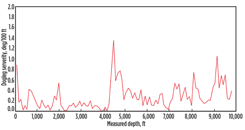
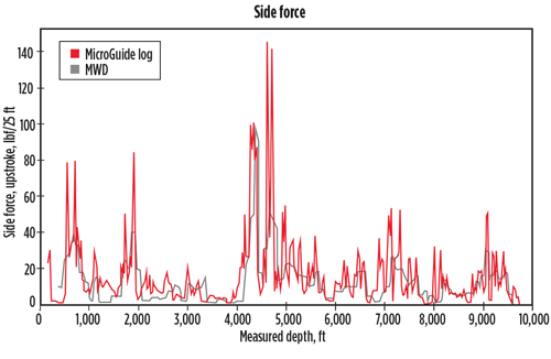
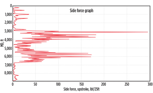
The initial DLS analysis provided by the MWD equipment stated that the DLS was no more than approximately 1° throughout the section, as shown in Fig. 3. DLS alone, however, does not provide a full picture of everything going on downhole, but MicroGuide also calculated side force. As shown in
Fig. 4., additional areas of high tortuosity were apparent between 4,640 and 4,690 ft, and this high tortuosity was the root cause of the rod pump system’s premature failure. Better understanding of the wellbore’s profile, which was made possible by the high-density data and obstruction analysis, enabled the operator to maximize its production and extend the life of the well. As an additional benefit, the operator achieved cost-savings by avoiding the average three workover operations required per year, due to the premature failures, as well as the associated lost production.
Another operator drilling in the Debuhr field, in Oklahoma, had been experiencing persistent rod guide failures on one of its artificial lift systems, with repairs necessary every 1.5 months for rod parting. The operator had used a standard rod guide design program and attempted to implement several different rod designs, but continued to encounter issues and up to 10 replacements. Further inspection revealed that significant sideloading against the tubing was causing the repeated fatigue failures, which were contributing to large financial losses. Each failure was averaging $5,000 to repair, causing up to two weeks of downtime, and yielding production losses of approximately 4 bopd. To remedy these losses and develop a better plan moving forward, the operator requested an in-depth investigation of the wellbore’s profile and condition.
Initially, the operator only had single-shot data, which were showing that the well had an inclination of less than 1.7°; as such, the well was assumed vertical, which aligned with results using a traditional MWD log. Using the MicroGuide system, however, allowed surveys to be analyzed at 1-, 5-, and 25-ft intervals for true high-resolution data logs. Gyrodata identified a significant inclination spike at 3,000 ft, MD, which had gone undetected using conventional MWD methods. After reviewing the tortuosity calculations from the MicroGuide system, it was clear that there were areas of compressive strength and buckling in the wellbore. These issues were causing the rod guide fatigue failures at 3,000 ft, MD, where significant sideloading against the tubing was occurring.
Using the MicroGuide system allowed the operator to obtain a much clearer and more accurate depiction of the wellbore’s condition by identifying the isolated dogleg at 3,000 ft, MD, Fig. 5. The high-resolution data improved modeling calculations, enabling development of a new rod guide design. After implementing the new design, the operator eliminated rod guide-associated failures. The system has, so far, saved the operator more than $50,000 versus the original costs of repair, as well as 70 days annually in workover and loss-of-production costs and downtime.
The energy industry will continue to discuss ways in which unlocking synergies between conventional equipment and digital technology will change business models and innovation paradigms. While many terms appear in the media with much greater frequency, the potential effects of niche technology offerings in the digital space cannot be discounted. At the intersection of advanced equipment and technology, Gyrodata has developed a unique offering for understanding areas of tortuosity and obstruction in the wellbore. As operators try to plan out more precise, more accurate wellbore placement by incorporating various other technology suites, they would be wise to think about the benefits of having high-density wellbore logging data to better inform their decision-making.
- Unlocking ultra-high-pressure reserves: Why Shenandoah is a milestone for deepwater engineering and advanced chemistry (March)
- State of digitalization in the oil and gas industry (February)
- FPSOs, reliability and gas turbine air intake filtration (February)
- Rugged, explosion-proof computers safeguard offshore rigs (January)
- The evolution of remote-controlled FPSOs (January)
- Halliburton’s ZEUS IQ™ powers the first fully autonomous fracturing platform with closed-loop automation (January)
- Subsea technology- Corrosion monitoring: From failure to success (February 2024)
- Applying ultra-deep LWD resistivity technology successfully in a SAGD operation (May 2019)
- Adoption of wireless intelligent completions advances (May 2019)
- Majors double down as takeaway crunch eases (April 2019)
- What’s new in well logging and formation evaluation (April 2019)
- Qualification of a 20,000-psi subsea BOP: A collaborative approach (February 2019)

