How intelligent well technology can maximize recoverable reserves
INTELLIGENT WELL COMPLETIONSHow Intelligent Well Technology Can Maximize Recoverable ReservesA long-term strategic approach is identifying the potential and limitations of developing new "intelligent" systemsBrian Drakeley, Business Development Manager, ABB Offshore Systems, Houston, and Neil Douglas, Subsea Systems Engineering Manager, Nailsea, UK The authors take a critical look at the overall subject of intelligent well technology in this presentation, starting with definition and scope of just what such systems comprise and how far they can go to meet the upper end of industry’s expectations. A principal discussion addresses reliability issues of intelligent systems, including introduction of a new proprietary well-control / communication system under development. Progress of a major ABB-group review is presented. And the important topic of "monitoring beyond the wellbore" is discussed, highlighting this as a major, much-needed development. The goal of the overall presentation is to give tangible information and food-for-thought – if not a definitive answer – to the question, "Intelligent well technology – the key to maximizing recoverable reserves, or just more headaches for the operators?" Introduction Much has been – and continues to be – written about intelligent well technology (IWT), but not everyone agrees as to what constitutes an intelligent well (IW). Some feel that merely the use of permanent downhole gauges (PDGs) that monitor and collect wellbore and/or reservoir data, constitutes an IW. Then there are others who believe that use of simple hydraulic-controlled, remote-operated, downhole-flow-control devices with only on/off position control but no downhole monitoring, should be considered an IW. A definition accepted by ABB, among others, is that an IW installation is one that includes all of the following capabilities:
But the technology faces much bigger issues than merely agreeing on a definition. Any new technology faces obstacles in gaining industry acceptance, least of all in the oil and gas industry, long known for its overall risk aversion (though there are some exceptions). Couple that with some well-publicized difficulties with some of the earlier IW installations and the result is that most systems now being installed can be characterized as low- to mid-end systems, i.e., with limited position control and little in the way of monitoring / diagnostic capabilities. Without doubt, early predictions by oil companies and others of the rate of acceptance of IWT have proven to be significantly overstated. Nevertheless, it is encouraging to find that, since the first installation in 1996, there have been close to 100 installations worldwide, with at least some form of remotely operated, downhole-flow-control device(s). However, to take full advantage of the benefits of the technology – i.e., improved overall recovery; increased / accelerated production; reduced well construction costs; reduced well-intervention frequency and costs; and reduced surface facilities – systems with greater functionality than the so-called low-end systems are going to be required for many of the world’s reservoirs. Some of the issues identified that, if addressed, will facilitate greater use of high-end / high-functionality IW systems are:
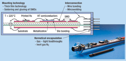
Addressing IW Reliability Issues The overall objective of the ABB Intelligent Well project has been – and continues to be – to ensure the provision of satisfactory system reliability and operational performance on a long-term basis for all well applications. To achieve this objective, systematic component criticality assessments and reliability performance simulations are applied as decision-support tools during the design process. This ensures that the end design is "reliability driven" and that any "reliability killers" have been eliminated. Of particular interest is that operators can be supplied with reliability predictions, along with commercial proposals for a variety of system configurations. System description. The company’s intelligent-well-control and communication system, (named ADMARC*-Advanced Downhole Monitoring and Reservoir Control) is based on an architecture which utilizes dissimilar redundancy and fault-tolerant design features to enhance system reliability. The downhole flow-control device (FCD) can be operated via electrical, hydraulic or electro-hydraulic actuation means. One of these operational means is selected as primary, the other as the secondary or back-up operational mode. In the unlikely event that the primary means undergoes a system failure, the back-up mode can be enacted. Sensors and data acquisition circuits at the FCD provide feedback on zonal production / injection status – e.g., pressure, temperature – to the operator, via the communications link. Also, diagnostic information on equipment condition in service is provided. The FCD also houses redundant electronic modules to ensure maximum system availability. The FCD is "fails as is" on loss of both hydraulic / electrical power, and the system is applicable to both production / injection wells. A back-up or remedial mechanical shifting feature is incorporated. Connection to the downhole components is typically via wet-mate couplers at the tubing hanger. The proprietary system’s FCD has fully variable choking capability, offering an almost infinite number of positions between fully open and fully closed. Precise control is easily achievable via internal, local-position monitoring sensors. In subsea applications, the subsea control module (SCM) houses the system’s interface card, and typically provides the required hydraulic services and the required 150-V DC power source, drawing very low power levels so as to have little or no impact on the subsea distribution infrastructure. There are two options for electrical power and communication transmission – either communications can be super-imposed on the power (COPS); or separate power and communications lines can be selected. The relative merits of each will not be dealt with in this article. High-temperature electronics. The basic version of the proprietary system described here utilizes electronics rated for 300°F (150°C). In addition, ABB is in the process of qualifying downhole electronics rated for 225°C. The higher rating is achieved via proprietary electronics manufacturing techniques, together with use of application-specific integrated circuits (ASIC) designed specifically for this application, Fig. 1. This work is both operating-company and European-government-agency sponsored.
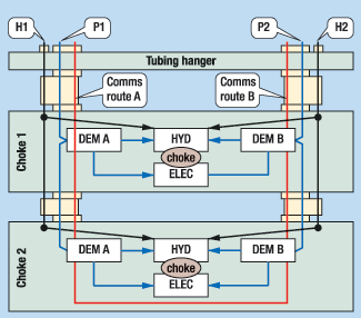
It should be noted that use of electronics rated far above actual well application ambient temperatures results in a direct increase in overall reliability – that is the driver for the development of HT electronics. The technologies being developed in this HT electronics program are also directly applicable to electronic PDGs. This supplies an alternative solution to improving PDG reliability – for those not convinced of the long-term reliability of the new-generation, downhole optical-sensing systems. Reliability expectations, simplified model. There does need to be some realism applied in setting reliability expectations for IW systems. The harsh installation / operating conditions make a zero-failure expectation over a 10 – 15-year life span basically unachievable. In determining the desired reliability of an IW system, a multitude of variables must be considered, balancing those such as equipment capital costs and available technology against the consequences of system failures. These variables will obviously change from one reservoir and field application to another. The company has a corporate group of scientists and engineers with expertise in the field of reliability. Starting in 1998, this group was charged with addressing the reliability issue of IWs. Although strictly addressing the ADMARC system, much of the ensuing methodologies and process improvements could apply equally well to all such systems, regardless of supplier. Fig. 2 illustrates the simplified model used in a dual-downhole, choke-completion application. The reliability performance figures generated therefore apply to the downhole components of the proprietary system, from the tubing hanger, wet-mate connectors down.
Reliability philosophy, approach, results. Principles of the reliability philosophy employed are:
A number of alternative system configurations have been analyzed using the methods and tools listed below; thus, a quantitative comparative assessment can be made of systems with various degrees of redundancy, component technologies, etc. Methods / tools used include:
Reliability study results are summarized by the following: FMECA: No unacceptable failure modes have been revealed, indicating a sound system design. Reliability predictions: Results are expressed as a percentage probability of survival (or MTBF) after a specific period of time under specified conditions, e.g., temperature. Reliability prediction numbers obtained should not be considered "absolute" due to the nature of the input data but, instead, be used to compare benefits of different architectures or system features. Component criticality assessment: The most critical components in the system have been identified, and their contribution to overall system reliability has been quantified. This also selects the "major" contributors to be easily identified for further reliability enhancement activities. Feature benchmark: A feature benchmarking exercise has been performed to quantify the effect of introducing various reliability enhancement features into the system design. The exercise demonstrates a clear benefit of selecting a highly redundant, fault-tolerant system design, Tables 1 and 2. The benefit has been further quantified by comparing the base case system to a "bare-bones" system, featuring single downhole electronics and flatpack umbilical . Interfacing with subsea systems. An area receiving increased attention within the industry is that of interfacing the downhole IW system with the subsea system. The two interfaces that have had the most exposure and attention are communications (data rates and protocols) and power delivery (voltage levels, power demand and regulation issues). ABB is a participant in the operator / service company sponsored Intelligent Well Instrumentation Standardization (IWIS) project that is working to update relevant ISO standards to include provisions for IW technology.
Reliability work conclusions, to date. The main conclusions reached so far can be summarized as follows: Reliability analysis provides an active decision tool that can be used throughout the entire design and development process. But absolute predictions for IW systems will not be possible with currently available data. The primary purpose of the process described is to gain comparative evaluations of system alternatives. There will be system faults – things will go wrong. The task at hand is to minimize the failure frequency and consequences of failure. Monitoring Beyond the Wellbore Downhole monitoring can essentially be divided into two market segments: 1) Wellbore sensing – permanent P&T sensors plus other well-fluids characteristics measurements, e.g., flowrate and watercut, and electrical / optical techniques; and 2) Reservoir imaging beyond the wellbore – micro-seismics (temporary and permanent), and resistivity, cross-well topography. Increasingly, operators are recognizing the value of monitoring beyond the wellbore, and some of the potential benefits to be accrued from micro-seismics are:
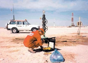
For ABB, the focus in the monitoring services segment is on micro-seismic data acquisition, processing and interpretation. Essentially, micro-seismic events are micro-earthquakes that occur in the reservoir as a result of fluid movement. But is it important to note that not all reservoirs are receptive to utilization of this technology. Most micro-seismic surveys performed to-date have been of the so-called temporary surveys type, typically performed for: hydraulic-frac-operation monitoring; drill cuttings injection monitoring; and trials to examine the potential for deployment of permanent surveys, i.e., proof-of-concept in specific fields. Of more significance to the future of this technology is current development work aimed at producing cost-effective and reliable, permanently deployed micro-seismic monitoring systems, Fig. 3. Such experimental systems are now beginning to be deployed in producing fields and we can expect to hear more on the results later this year.
Conclusions The company has taken a long-term strategic approach to the IW market. The proprietary system development project remains in the development phase as qualification testing continues, now with further client and governmental support. The overall focus remains solidly on improving system availability prior to bringing this high-end system to market. The so-called "holy grail" of the permanent monitoring business (monitoring beyond the wellbore) is being addressed through development of permanent micro-seismic monitoring systems that capitalize on the company’s experience in temporary monitoring. Finally, the promise of improved macro-economic tools for evaluation / quantification of the benefits of intelligent well technology to the operators brightens the future expectations for greater utilization of this entire technology field – no matter which definition you subscribe to!
|
|||||||||||||||||||||||||||||||||||||||||||||||||||||||||||||||||||||||||||||||||||||||||||||||||||||||||||||||||||||||||||||||||||||||||||||||||||||||||||||||||||||||||||||||||||||||||||||
- Advancing offshore decarbonization through electrification of FPSOs (March 2024)
- Subsea technology- Corrosion monitoring: From failure to success (February 2024)
- Driving MPD adoption with performance-enhancing technologies (January 2024)
- Digital transformation: A breakthrough year for digitalization in the offshore sector (January 2024)
- Offshore technology: Platform design: Is the next generation of offshore platforms changing offshore energy? (December 2023)
- 2024: A policy crossroads for American offshore energy (December 2023)
- Applying ultra-deep LWD resistivity technology successfully in a SAGD operation (May 2019)
- Adoption of wireless intelligent completions advances (May 2019)
- Majors double down as takeaway crunch eases (April 2019)
- What’s new in well logging and formation evaluation (April 2019)
- Qualification of a 20,000-psi subsea BOP: A collaborative approach (February 2019)
- ConocoPhillips’ Greg Leveille sees rapid trajectory of technical advancement continuing (February 2019)


