Evidence-based initiative improves guided sucker rod longevity
It can be argued that at some point in their productive lives, the majority of unconventional wells will rely on beam pumping to sustain production flow. Compared to other artificial lift technologies, sucker rod-enabled beam pumps for decades have proven to be one of the most viable solutions for maintaining production efficiency, as reservoir pressures decline over time.
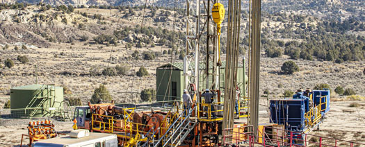
While sucker rod pumping (SRP) is widely accepted for its reliability, versatility and general affordability, the technology can be highly susceptible to tubing and rod wear-induced downtime, especially in deviated well paths.
Root cause analysis has more than 50% of SRP failures traced to metal-to-metal contact between the production tubing and rods, resulting in up to 85% of well maintenance costs, not to mention lost production revenue while the well is off-line.
While equipping the rod string with sacrificial plastic guides has been the go-to method for mitigating wear, the design and placement of same has been an inexact science, at best. Owing to the diversity of the various plays, including intrinsic downhole characteristics, individual operating parameters, key performance indicators (KPI) and economic frameworks, the often-arbitrary application of what traditionally has been an off-the-shelf component does not provide a universally optimized level of protection.
DATA ANALYSIS
To address these shortfalls, a data-driven initiative systematically combines real-time data collection with historical insights and straightforward graphic representation to recommend guided rod string designs, customized for targeted well or field conditions. The multifaceted program, which includes a number of patented services and technologies, begins the guided rod design process with well site tubing scans, using a combination of the exclusive Isolog and electromagnetic inspection (EMI) technologies.
The data collected onsite are combined with well-specific information and encapsulated in the proprietary Rod Guide Advisory Program (RGAP), the only software built on empirical data to extend mean time between failures. The platform considers all the pertinent metrics and is a crucial step in the recommendation of a fit-for-purpose guide design.
The latest results in an ongoing Eagle Ford program show the onsite tubing inspections in tandem with output from the software, enabling an operator to extend run times by 78% on average. In addition to maintaining steady production flow, while reducing the number of workovers, the initiative has saved the operator up to $2.6 million in rod, guides and tubing replacement costs, Fig. 1.
Wear-inducing problems. Extended-reach wells with high dog-leg severity (DLS) at kick-off, have aggravated the abrasive dynamics that generate tubing and rod wear in SRP operations. In wells using reciprocating pumps, the continual up-and-down movement of rods against tubing scrapes away metal, eventually rendering certain tubulars unusable. Additionally, along with geological conditions, corrosive elements in production fluids can impact the rate of wear.
The programmed deviation and associated DLS of unconventional wells intensify wear, inducing tendencies, which create side loads that can propagate buckling and compression of both tubing and rods. Also identified among the primary contributors to tubular failures and costly workovers are improperly designed and/or erratically spaced rod guides. That recognition drove the artificial lift segment of Tuboscope’s broader production optimization group to adopt an analytical, site-specific approach to rod guide design and placement.
The methodic exercise aimed at keeping beam pump wells on-line longer commences with the WellChek well site diagnostic service, which inspects tubing condition at the well site and captures sequential data coming out of the well. The scan results are uploaded into a proprietary database for subsequent alignment with deviation data, the previous rod design, failure history and well characteristics to modify the proposed string design to extend run times and asset value.
Onsite tubing scans. Typically, operators conduct routine inspections during workovers to identify tubing that has worn or corroded to the point of being unfit for continued service. Iterations of the mobile inspection service have been around since the 1980s, often overlapping with in-plant sucker rod inspection, where one of the primary objectives is to refurbish pulled rods for return to the field.
On-site scans combine EMI with proprietary technology that measures remaining tubing wall to more accurately detect longitudinal defects and other signs of wear inside the rod. By contrast, contact EMI produces high signal quality to identify and measure corrosion or similar flaws in the transverse plan of the tubing body. The twin inspection technologies on location deliver far more accurate tubular scans than those using only non-contact EMI inspection equipment.
During an inspection, wall loss detection equipment measures the tubular walls, and specifically the thickness of the remaining metal. As the measurements are gathered, each joint is color-coded to denote the percentage of wear, as per API standards (yellow: 0-15%, blue: 16%-30%, green: 31%-50%, and red: 51%-100%). A report is issued immediately after the inspection, wherein the customer is advised how many joints were scanned, and a sequential breakdown of the top-to-bottom condition of the tubing coming out of the wellbore. The clearly discernible identification of issues is the foundation for the subsequent rod string design recommendations, based largely around the well operator’s targeted run time.
The scan results are instantly uploaded to a secure online depository of the client’s wells that they can readily access to see the real-time condition of their tubing, either on a well-by-well basis or all the wells on a pad or field. A summary of overall downgrades allows customers to visualize any field-wide failure patterns that need to be rectified.
Engineered rod guides. The installation of sucker rod guides typically is the first reactive measure taken upon the identification of wear. These plastic components are molded onto the rod and designed to wear out rather than the metal. Historically, however, “designed” has been a misnomer, as rod guides generally have been treated as a relatively standardized bolt-on component. Given the disparate characteristics, often even between wells in the same field, the one-size-fits-all approach to rod guides does not offer a suitable level of protection in all well environments. The deep and high-temperature conditions in the Eagle Ford and Bakken shales, for instance, may require different levels of protection than elsewhere.
The patented New Era portfolio of sucker rod guides advances the product’s evolution from simple metal scrapers for downhole paraffin control to engineered technologies tailored for specific well conditions. The composition and shape of the plastic mold can vary to meet distinctive temperatures and fluid properties. The number of guides, placement and spacing along the string, derived from the RGAP software, is determined from deviation measurements, well history, and other key factors.
Though an evolving research and development program directed at the composition and shape of the plastic molds, themselves, has been in effect for years, the development of the production optimization initiative and the growth of deviated shale plays provided opportunities for improvement.
The mold material comprises thermoplastics with a useable temperature range from 140°F to 500°F. The small pellets are melted down and injected under high temperature and high pressure into a cavity and enclosed around the rod, where they harden under cooling and form the guide. As part of the internal quality control process and the routine analysis of new material, bend tests are conducted to measure flexibility.
One of the key factors in determining the wearability potential of a particular guide, aside from the material and shape, is the volume of plastic in the stand-off between the tubing and connecting coupling. The plastic volume and the corresponding level of protection increases with the length of the guide and the width of the vanes, which are the blade-like molded portions of the guide that extend from the body to enable contact with the interior surface of the production tubing. When engineered correctly, the run time will have been extended appreciably before the material wears out and allows metal-to-metal contact, thereby paying back the initial guide investment.
To quantify the plastics wear potential, a series of tests is conducted under simulated conditions and recognized industry protocol. Complementing the industry-standard dry wear tester to examine abrasive wear is a specially engineered wet abrasion tester. It uniquely measures plastic wear under parameters more representative of downhole conditions. Subsequent tests include autoclave and immersion testing to determine chemical and temperature resistance and ensure that the plastics remain stable under various simulated production fluids and gases, as well as elevated temperatures and pressures. A series of impact tests, likewise, probe the ability of the plastic to withstand handling and production operations.
Guide design considerations. The primary operational criteria in designing fit-for-purpose rod guides revolves around the interplay of erodible wear volume (EWV) and hydraulic efficiency, with the ultimate consideration of spacing along the rod to address side loading, DLS and other wellbore issues.
Crucial to the effectiveness of a guide, the EWV is defined as the amount of guide material outside the OD of the coupling, which is susceptible to wear before the coupling contacts the tubing. The EWV will vary, based on the length of the guide or the shape of the vanes on the guide. Since larger couplings reduce the amount of stand-off, the coupling size directly impacts the effective EWV between the coupling and tubing. Moreover, cutting edge work on enhancing hydraulic efficiency has demonstrated that a standardized rod guide design offering high EWV, in tandem with a straight vane and tapered end, helps decrease the impact of flow restrictions. As part of an initiative to elevate hydraulic efficiency in guide designs, the artificial lift group was among the first to test the impact of the turbulence on rod guides, resulting in the industry’s first low-drag guides.
To evaluate the impact of the guide design on the minimum polished rod load, the design phase includes subjecting the guides to a hydraulic drag test to examine the effect of fluid dynamics, particularly turbulence resulting from flow disruption. The apparatus is configured to enable flow to be reversed, whereupon air is injected with any resulting gas bubbles indicating breakouts around the guides.
Without doubt, the precise spacing of guides to resist wear-inducing characteristics along the wellbore is essential for maximizing run times. It had been widely assumed that guides need only be installed at well depths identified as having elevated side loads, which, along with measured depth, is influenced by axial loading, tubular buckling tendencies and the DLS values. Subsequent investigations, however, disclosed that even in the absence of high side loading, certain inclination angles can propagate wear tendencies and justify the placement of guides elsewhere along the rod string.
Standardized spacing with the guide molded onto the rod builds off internal studies using clear tubing. In these investigations, buckling was simulated on one end of the rod to identify the initial point of steel and tubing contact, with the spacing set accordingly. The standardization guidance includes using guides placed close to the end of the rod, thus limiting movement and potential contact with the tubing. Guided rods require additional load to buckle and can be used in place of typical sinker bars, providing sufficient quantities for tension and still offer wear protection. Based on the targeted run life, the well-specific guide design, including the material, guide type, quantities and the depth placement, are dictated by output from the proprietary RGAP platform.
Corrosion control. Conjointly with the rod guide design initiative, an exclusive suite of specially formulated internal plastic coatings mitigates corrosion arising from dissolved gases, brines, and production chemicals, as well as in-situ microbial growth. The tubing coatings adhere well to the internal tubing surface and serve as a barrier between the steel substrate and well fluids.
Indications of corrosion typically crop up during tubing scans, which lead to coating recommendations derived largely from an operator-provided list of treating chemicals and the associated safety data sheets. As with rod guides, a variety of formulations enables coatings customized for specific producing environments. For example, owing to a notoriously high water cut, significantly more coating is run in the corrosion-prone Permian basin than elsewhere.
To establish the most harmonious relationship between corrosion control and wear, guides are evaluated against different coating formulations as part of the wet abrasion testing. The ensuing evaluation of the interaction between the guides and coatings provides data for recommending the optimum combination for the targeted operating conditions.
Data-enabled guide design. The proprietary rod guide advisory software is unique in that it is built upon some 20 rules, based on the patterns observed from actual field test results with distinctively simplified visual representation. The foundation of the platform includes case studies from hundreds of wells that were physically measured, analyzed and tracked, to identify any trends and specific characteristics that contributed to excessive rod and tubing wear.
Included as part of the rod optimization service, a dedicated team of engineers run the program in-house, using the output to recommend a rod string guiding program, based on empirical well-specific data and the operator’s targeted run time and fiscal situation. The program captures the tubing scans, workover histories, previous failures, deviation surveys, production data and well characteristics, essentially capturing as much well information as possible. The recommendations also consider calculations derived from licensed access to industry standard rod design programs. Those programs, however, are limited strictly to guide placement, based on side loading and, unlike RGAP, do not include myriad guiding rules for optimization.
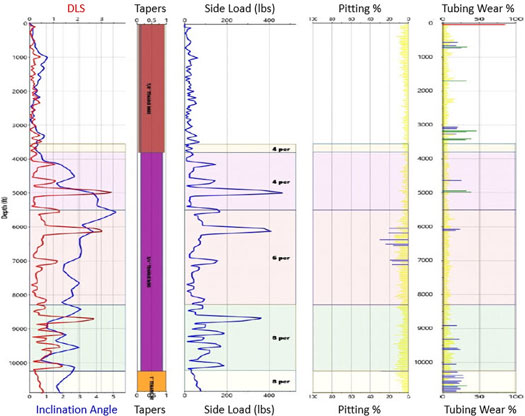
The resulting rod guide design recommendations are singularly represented in side-by-side plots that provide clear evaluation of the tubing scan, failure history, rod string, guide caliper reports, along with inclination angle, DLS and side load. The WellMap representation component enables operators to easily visualize the problem areas and mitigating strategies at any point in the well.
The efficacy of the software-enabled rod guide optimization strategy to extend SRP integrity and reduce material costs is exemplified in a continuing program for an established operator in the South Texas Eagle Ford play, where more than 700 horizontal wells use beam pumps for artificial lift. Typically, the pumps are landed at 5,000-12,000 ft, true vertical depth (TVD), with bottomhole temperatures of up to 300°F. There, along with deviation-related issues, they deal with corresponding challenges like paraffin deposits, corrosion, slug flow, foamy gassy fluids and high solids content.
Eagle Ford recap. Prior to initiation of the optimization program in 2016, the operator’s reliance on guide material comprising polyphthalamide (PPA) in designs providing low EWV had resulted in rod and tubing wear-related failures and added replacement costs well before the targeted four-year SRP run time. The optimization sequence began with an evaluation of scans from 50 wells, employing the operator’s previously standard guide designs to establish a baseline performance before installation of the engineered guide program.
Pre-optimization, the average run time of these wells was 529 days. Following installation of the software-recommended guide design, the run times on half of the 50 wells jumped to 708 days, a 78% improvement on average, with a median 49% reduction in overall failure rates. Most of the wells that failed to exceed the original run times were pulled for pump failures, offset completions and other non-wear-related issues. Only 10 of the 25 wells that did not meet expectations were pulled, due to premature tubing and rod wear. In these instances, all wear-related failures were in sections of the well with re-run rods that had been evaluated visually at the well site.
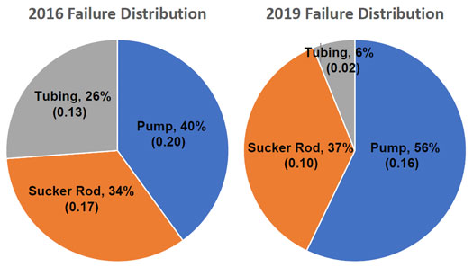
Comparative analysis between the two production periods in a specific example well shows 154 rods being replaced after the second pull, compared to 293 rods discarded in the initial production evaluation period, Figs. 2 and 3. Tubing inspected as “red,” or wholly unusable, dropped from 11% to 0.03%, while on the other extreme, hardly worn yellow band tubing increased from 52% to 85%.

Over the past five years, it has become the operator’s standard practice to proactively utilize the software-generated rod guide design recommendations to mitigate wear and associated problems. Run times and failure rates have steadily improved, as more wells are worked over.

- Regional Report: Brazil reaches for new heights in 2026 (March)
- What's new in production: Things go better with Coke (February)
- Before OPEC, there was Texas: A better path for Venezuela’s oil revival (February)
- International E&P shows the way forward (February)
- What's new in production: Welcome diversion? (December 2025)
- Flexibility and modularity enable tailored solutions for challenging shale plays (December 2025)
- Subsea technology- Corrosion monitoring: From failure to success (February 2024)
- Applying ultra-deep LWD resistivity technology successfully in a SAGD operation (May 2019)
- Adoption of wireless intelligent completions advances (May 2019)
- Majors double down as takeaway crunch eases (April 2019)
- What’s new in well logging and formation evaluation (April 2019)
- Qualification of a 20,000-psi subsea BOP: A collaborative approach (February 2019)

