Understanding collapse resistance of casing strings with different cementing configurations
Salt creeping movements create three loading mechanisms that may result in a production casing failure: 1) uniform loading; 2) non-uniform loading; and 3) shear loading. When dealing with salt formations in the oil and gas industry, the most common practice is to choose between two casing strings (pipe-in-pipe) or an individual high-collapse casing column.
To understand the differences between the two casing columns, an experiment was initiated that consisted of two different laboratory test set-ups. The first set was a collapse test performed in a high-pressure vessel under hydrostatic conditions, to reproduce uniform loading. The second test set, which was one of the first experiments of its kind, reproduced punctual non-uniform and shear loading. It was conducted with a mechanical press, equipped with an ad-hoc designed indenting tool that simulated the effect of hard formation inclusions in salt layers, acting on the casing’s external surface.
To simulate real stress conditions, like the ones found in the well, tests were performed on three different pipe-in-pipe configurations: 1) centered annulus and perfectly cemented; 2) 10% stand-off and perfectly cemented; and 3) centered annulus with contaminated cement. These full-scale tests were intended to improve the understanding of collapse resistance and will inform the design of pipe-in-pipe, cemented casing strings going forward.
BACKGROUND
Salt formations are a typical trap for hydrocarbons. The interest in these types of traps has grown over the last several years, with operators facing new technical challenges to drill through salt formations, and to manage the associated loads. Perturbations in salt formation during drilling operations lead to time-dependent rock deformations. This phenomenon is known as creeping. The chemical composition of salt and the stresses acting around the formation generate different salt creeping behaviors. In fact, the rate at which salt creeps may vary, depending on salt composition, water content, presence of impurities (such as interbedded clay), temperature, depth and differential stresses.
Three different load modes need to be considered for casing design in creeping formations: 1) uniform loads; 2) punctual loads; and 3) shearing loads. Salt creates a uniform load on the external surface of the casing, similar to hydrostatic pressure generated by a fluid with the same density of the equivalent overburden gradient. This is the most common approach for casing design purposes.
Due to actual non-uniform distribution of cement sheath and bad centralization of the pipe inside the borehole, some punctual loads are generated at discrete locations on the casing external diameter. Another cause of punctual stresses is hard formation inclusions present inside salt domes.
The curvature of the wellbore and the lateral movement of the salt could potentially lead to casing bending. This bending could generate casing failure or string ovalization, with the consequent loss of well access. This condition especially occurs at the salt formation interfaces. The determination of this type of loads is extremely difficult to calculate and foresee, but its impact should not be underestimated.
The two main approaches to overcome well collapse issues in the oil and gas industry have been the use of concentric cemented casing strings (pipe-in-pipe, PIP) or casing with proprietary high-collapse grade. The study described in this article focused on the first option and evaluated the combined effect of casing and cement in terms of collapse resistance.
PIPE-IN-PIPE ASSEMBLY
In literature, a common approach to evaluate the combined effect of running one casing string inside another is superimposing the collapse ratings of the individual strings, considering a scaling factor according to the following equation:
Rs = K(RI+R0)
Rs = Combined collapse rating of the system
RI = Inner pipe collapse rating
RO = Outer pipe collapse rating
The multiplier “K,” as found in literature, is a reinforcement factor with a maximum value of 2.03, which changes depending on casing strings, centralization and cement job quality. The K factor is a function of the D/t ratio of the respective casing strings, and the K factor decreases as the D/t ratio increases. If both casing strings are poorly cemented, they can act independently, leading to a minor synergic effect and resulting in a K factor less than 1.0.
One of the main objectives was to reproduce salt’s uniform loading on the pipe-in-pipe assembly, in order to calibrate the K factor. A proper definition of the K value can reduce the uncertainties on this parameter. It leads to better tubular selection, in terms of sizes and grades, and subsequently to more accurate well design accuracy.
The second objective of this study was to explore the behavior under punctual loads and their effects on casing resistance and cement sheath integrity. Regarding external pressure loads, extended well design practices usually only consider uniform loading, given that challenging non-uniform loads are difficult to include in a procedure, due to the limited knowledge available and the complexity to build a consistent and reliable simulation tool.
Based on field experience and the results of the tests described in this article, criteria to also evaluate non-uniform loading conditions could be included as part of well design procedures.
FULL-SCALE TESTING
To evaluate the performance under uniform external pressure and punctual external loads, two different full-scale test set-ups were designed. Tests were conducted over a two-year period, in multiple batches, covering a total of eight samples under uniform loads and six samples under punctual loads.
The uniform external pressure set-up was similar to the one used for a collapse test, according to API TR5C3:2018, which consisted of mounting the samples inside a pressure vessel, with an internal diameter of 15 in., a minimum sample length of 6½ ft and a maximum operating pressure of 33,700 psi. Pressure over time was recorded during the tests, which were halted when a pressure drop was detected. The punctual external load test was performed with a mechanical press, up to the maximum available load of 575 kips and measuring load versus displacement charts. An indentation tool with a tip radius of 2 in. was used to reproduce punctual loads.
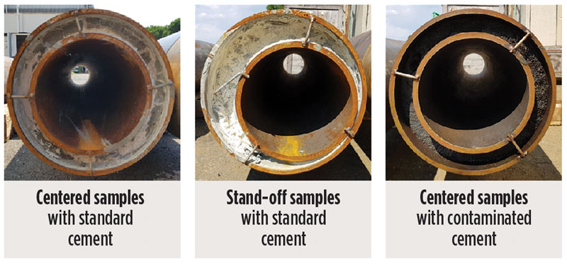
Specimen configuration and sample preparation. To simulate real-world downhole stress conditions, including reference and worst-case scenarios, tests were performed on three different specimen configurations: 1) a perfectly concentric casing, with standard cement slurry in the annulus; 2) a perfectly cemented configuration, with a 10% stand-off; and 3) a configuration simulating the effect of a poor cement job or contaminated cement, Fig. 1.
The first specimen represented the best conditions achievable while cementing, setting the reference case. The second specimen simulated centralization issues. In order to maximize the centralization effect, samples were manufactured with an extreme stand-off. The third specimen aimed at evaluating the impact of contamination with oil. Contamination often occurs, due to displacement prior to cementing or at mud-cement interfaces. The tubular geometry and materials were defined, considering maximum pressure vessel capacity of 29 ksi, verified by preliminary FEA analysis. The final assembly configuration was:
- Outer pipe: 133⁄8-in. 68.0# L80.1
- Inner pipe: 95⁄8-in. 43.5# L80.1
The length of the samples subject to external pressure tests was 8.2 ft, to comply with API TR5C3:2018 requirements, while the length of the samples tested for punctual loads was limited to 4.6 ft, due to the limited space inside the press. In the case of uniform external loads, two samples were manufactured and cemented for each specimen configuration.
Regarding the cement, a real slurry recipe, including an expanding additive, was used. Samples were cemented vertically, injecting the cement through a 2-in. pipe from the bottom, to achieve better displacement. The third configuration used a mixture of this slurry and 4% volume of oil. Cement slurry density was 15.8 ppg. To characterize the properties of the cement, 2-in. cubic molds were subject to compression tests. Average resistance for standard cement was 3,770 psi, while contaminated cement was 2,900 psi.
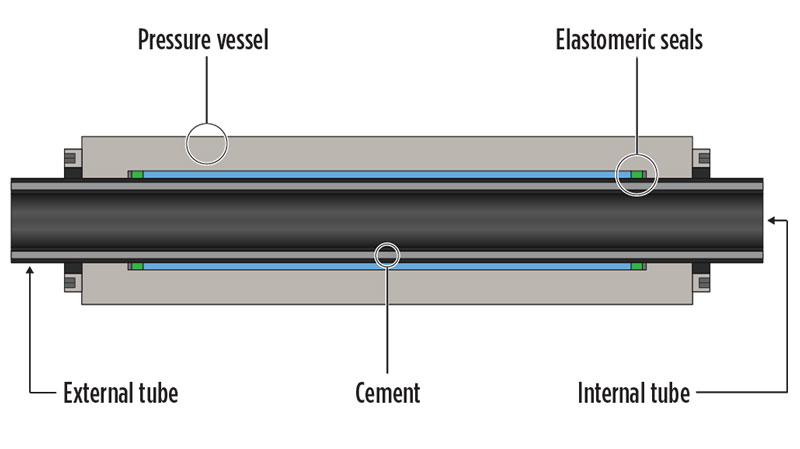
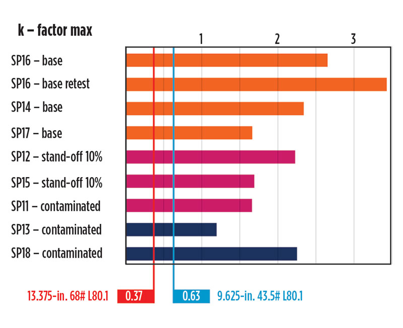
Full-scale test results for uniform loads. The pipe-in-pipe assembly was mounted in a pressure vessel, and the annulus between the sample and the vessel was pressurized, Fig. 2. Sealing was obtained with specifically designed elastomeric seals. Results obtained were presented in terms of the K-factor, a normalization based on the individual collapse resistance of pipes. The summary in Fig. 3 shows the test, plotting maximum K-factor. There was a significant dispersion between samples. The dashed lines show individual collapse resistance of the tubulars. The worst-performing assembly had more collapse resistance than the combined resistance of individual pipes. The main results concerning the uniform loads applications showed the possibility to determine a real K value. Based on the test results, more than 50% of samples showed a K value higher than 2.
However, if considering the worst performance among all the tested samples, the K factor was around 1.6-1.7, which represented a reliable value for all configurations, bearing in mind the uncertainties encountered during the tests and the amount of samples for each configuration. The collapse failures that occurred at the edge of the samples reproduced the interfaces between fluids and cement in the annulus that often occur at the top of the cemented area or in areas with poor cement boundaries. Cementing a tie-back inside an installed casing would improve the quality of the cementing job, leading to an assembly similar to a centralized casing with standard cementing specimen. This proved to be an important factor to enhance the collapse resistance of the production casing in salt formations.
Full-scale test results for punctual external loads. The pipe-in-pipe under punctual loads test was designed ad-hoc and was the first test of its kind in the world. Assembly, set-up and execution of the test for punctual external loads were easier than in the case of the uniform external pressure test, and more stable and repetitive results were obtained.
Following the same pattern used for uniform external pressure, three specimen configurations were considered, with two samples per configuration. These samples were shorter, in order to fit the mechanical press. No edge effects were expected. All the tests were performed up to maximum press capacity, measuring both load and displacement.
- Concentric–standard cement, two samples
- Standoff 10%–standard cement, two samples
- Concentric–contaminated cement, two samples.
Samples with stand-off were tested with two different positionings in the press: 1) one with maximum cement thickness on the bottom; and 2) one on the side. The low resistance of contaminated cement was critical for the tests. Significant deformations occurred in the seal regions, ending the tests prematurely. The results showed that samples with stand-off samples were the ones with higher stiffness, while the samples with contaminated cement showed lower stiffness.
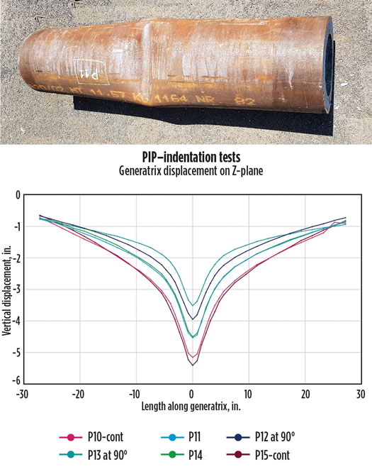
In all cases, the shape of the indentation was measured along the upper generatrix after removing the samples from the press, Fig. 4. Deeper and wider indentations were found in the samples with contaminated cement. The smallest indentation penetration was shown in the sample with the stand-off lying in the horizontal axis.
FEA MODEL DEVELOPMENT
FEA was used during the test set-up definition to define the specimens’ geometry, based on the testing facility capabilities. Two different models were built: 1) for uniform loads; and 2) another for punctual loads. Both models shared most of the features, such as assembly configuration, material, constitutive laws, and contact definitions. Load models differed in each case, since they were related to the type of test and simulated conditions.
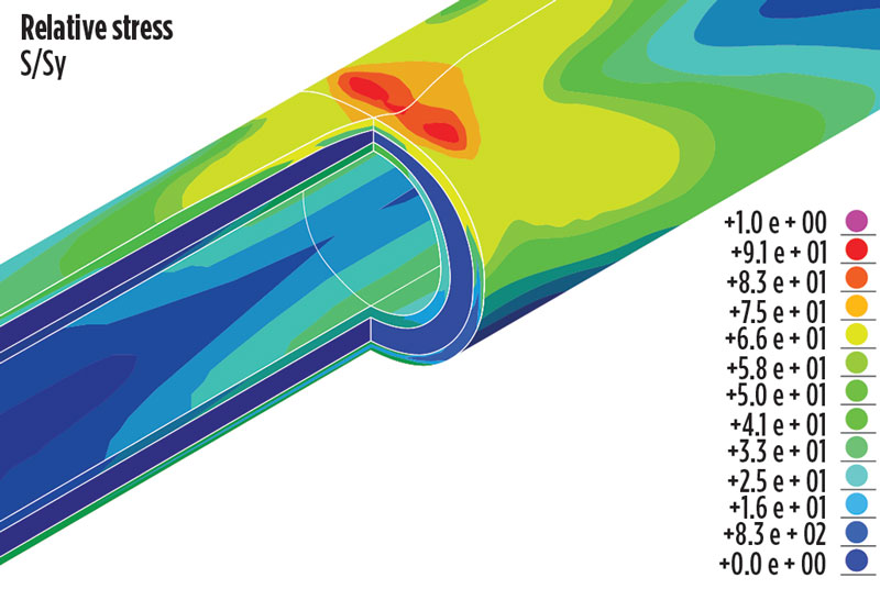
For the punctual loads model, FEA results exceeded testing by more than 100%, Fig. 5. Post-test analyses highlighted that, after every short initial phase, cement in the loaded region was completely cracked and shattered. Various modeling techniques were considered to find the best fit. Replicating this behavior through numerical models was very difficult, since there was a steep drop-off in load bearing capacity and related softening of the material.
Even when, from a quantitative point of view, the model for punctual loads was not able to properly capture the load displacement evolution, from a qualitative point of view, it represented the deformations shown during test. In the non-symmetric configuration, with stand-off in the horizontal axes, deformations were properly predicted, with the skew shape at the inner diameter.
Additionally, FEA allowed for investigating the behavior of cement with several damage models. Through FEA, it was also possible to define how displacements at the outer diameter of the assembly transferred to the inner diameter, which becomes critical when using tools in the well. The cemented region, while damaged, showed a significant capacity to absorb deformation. For example, an indentation depth of 0.5-in. on the outer diameter restricted only by 0.15-in. the borehole.
Once the tests were completed and the FEA models were fine-tuned, results were extended by two additional processes. The first one was to extrapolate the results from the uniform loads to other assembly geometries. The second one addressed the punctual loads model, to evaluate contact pressures. Punctual loads contact pressure was evaluated for a specific assembly and for different indentation radiuses, to define an interpolation table used for production casing design.
Samples with stand-off showed the highest stiffness, partially due to their non-symmetric geometry; there was a thick cement mass on one side and a high thickness of steel on the other. The latter was comparable to the sum of the two individual tubular thicknesses.
Also, the samples with eccentricity in the horizontal axes showed the highest stiffness, due to high resistance to hoop stresses where the two steel wall thicknesses were almost coupled. These tests only considered the structural resistance of the assembly and did not make any consideration about cement sheath integrity. Therefore, centralization quality did not contribute to the worst-case scenario from a structural point of view. Further tests could be implemented, to investigate the behavior of the cement and its effect on the overall system resistance.
DESIGN FORMULA
The impact of uniform and punctual loads may be approached with a holistic methodology by defining an equivalent external pressure acting on the column. By superimposing the effects, an equivalent uniform pressure was defined as the sum of the contribution of uniform external loads and punctual loads, resulting in the following formula:
Peq=(Pu+Pp Ku /Kp)≤ (Ku )(RI + RO)
Where:
Peq is the equivalent pressure, including uniform and punctual contributions
Pu is the uniform pressure used for design
Pp is the punctual pressure used for design
Ku is the k-factor, evaluated from full-scale testing, under uniform loads
Kp is the K factor, evaluated using FEA, under punctual loads.
All results obtained from both full-scale testing and FEA were included in the equation, which defined the onset of failure for a cemented concentric assembly. During well design, this equation can be used to verify whether the individual tubular collapse ratings are suitable for the application. This formula has not been validated at the field yet.
CONCLUSIONS
The main objective of this full-scale test experience was to analyze the traditional definition of the reinforcement factor of a pipe-in-pipe assembly (K factor value). A similar approach allowed for the definition of a K factor that now also considers punctual loads.
Following full-scale testing and FEA analysis, the results converged to the definition of a new design equation proposal that takes into account both uniform and punctual loads during the casing design.
An additional consideration was made regarding the trade-off between the use of two concentric fully cemented columns and a single pipe with proprietary high collapse steel grade.
Identifying the cases where two concentric cemented columns might be an over-design and could be replaced by an individual high collapse tubular could lead to clear advantages in terms of costs, operations, complexity and optimal well section geometries.
ACKNOWLEDGEMENT
The content of this article was extracted from OTC paper 30895-MS, “Cemented casings collapse resistance enhancement: Full-scale experience,” prepared for the 2020 Offshore Technology Conference. Due to Covid-19, the physical event was not held. The official proceedings were published online, May 4, 2020, at http://www.otcnet.org
- Simplified intelligent completion architectures improve zonal control economics (May)
- From post-mortem to real-time: A scalable approach to fracture diagnostics (May)
- The value of all-electric intelligent completions (April)
- Completions in the digital age: A true end-to-end approach (October 2025)
- The power of less: Surface pressure containment ecosystem autonomously delivers continuous sanding with fewer pump swaps (October 2025)
- A decade of excellence in the Middle East (October 2025)
- Subsea technology- Corrosion monitoring: From failure to success (February 2024)
- Applying ultra-deep LWD resistivity technology successfully in a SAGD operation (May 2019)
- Adoption of wireless intelligent completions advances (May 2019)
- Majors double down as takeaway crunch eases (April 2019)
- What’s new in well logging and formation evaluation (April 2019)
- Qualification of a 20,000-psi subsea BOP: A collaborative approach (February 2019)

