For as long as our industry has been drilling to extract oil and gas, we have had to address well control. The concept is a simple one: maintain control of the pressure in the well, so that the flow of fluids into and out of the wellbore is always as intended. The practice of maintaining that control is clearly not simple, or we would never see well blowouts, and companies such as Wild Well Control would not exist.
Fundamentally, pressure control is provided through a series of barriers, some temporary, such as the column of drilling mud used to hold pressure in the well, and some permanent, such as the steel casings and cement that finalize the conduit, which is formed to isolate the well from the environment and allow production of the oil and gas from the reservoir in a safe and controlled manner. If any of these barriers fail, then a well control problem becomes more likely to occur. This article is focused on the design of those permanent barriers and those that are formed through setting materials, such as cement and resin.
WELL CONSTRUCTION BASICS
While an oil well is being drilled, drilling mud, typically heavier than water, is used to form a column of fluid that keeps the pressure at the bottom of the hole higher than the surrounding rock, preventing pressure from escaping the earth. A series of steel pipes, or casings, is inserted into the hole to maintain hole stability. These casings are cemented in place by pumping cement into the space between the steel pipe and the hole that’s just been drilled. Once the cement cures, the combination of steel casing and cement provides a permanent barrier that isolates the wellbore from the environment. The depth of the well is extended progressively, with successively smaller casings being inserted and cemented in place until the required depth is achieved.
So far, the discussion above has referred to the steel casings and cement as permanent barriers. They are permanent when compared to the temporary barrier of drilling mud, which is removed once the well is complete. However, the design of both steel casing and cement barriers governs how long they last and how “permanent” they become.
Steel casings degrade over time, usually through corrosion. The cement barrier also degrades over time. Over the life of an oil well, the pressure in the wellbore changes, either through a natural process of decline over the well’s life, as removal of oil and gas depletes the reservoir and lowers its pressure, or by human interaction with the well. Well production is often halted deliberately to allow for maintenance of equipment or to allow for intervention activities that aim to improve production over the life of the well. These interventions result in the temperature and pressure, and as a consequence, the loads acting on the cement changing over time. Cement, as a material, is not particularly suited to being subjected to cyclic loads. The cement, or the bond between the cement and the steel casing, can crack and fail when subjected to cyclic loading. Failure of the cement barrier can create a leakage path forming from the reservoir to the environment, compromising safety and leading to environmental damage.
The design of the cement has a significant bearing on its ability to withstand cyclic loading, and the cement properties can be altered to best suit the particulars of any given well. However, the longevity of these cement barriers, and their ability to withstand cyclic loading, has sometimes not been given the attention it deserves.
In some circumstances, alternative materials, such as resin, are used to supplement the cement barrier, because they possess enhanced mechanical properties. However, as with cement, the resin properties also must be properly matched to the loading that is prevalent in each particular well scenario.
Wild Well Control uses its advanced computer simulation to enhance cement and resin barrier designs. The results of the advanced computer simulation are provided to the internal team of cementing experts at CSI Technologies. The experts at CSI Technologies recommend design changes and perform laboratory evaluation to validate the advanced computer simulations. Using a team of cement experts and advanced computer simulation abilities, failure of cement and resin designs can be predicted, and design optimization can extend the life of the barrier.
Simulation-enhanced barrier design. Finite element analysis (FEA) and computational fluid dynamics (CFD) can be used to better understand cement and resin behavior, and, as a result, barrier designs enhanced to provide better life of well performance. Looking firstly at cement, a multi-step approach is recommended to ensure the FEA simulations are thoroughly validated.
Step 1 - Material characterization. Some modern FEA tools have sophisticated material models. However, they are only of use if the materials are characterized properly. The first step in this process is to conduct a wide range of laboratory tests to thoroughly quantify the various mechanical properties that are essential for the FEA. Tests to determine compressive strength, tensile strength, elastic modulus, Poisson’s ratio, impact resistance and bond strength are all carried out in the laboratory.
Step 2 - Small-scale testing. Once the material characterization tests are complete, an FEA model can be constructed. Further tests are carried out at small scale. The design of the test varies from case to case, but the aim is typically to model the interaction between the cement and the steel casing. It also can include the interaction of the cement and formation. In particular, the aim of the test is to subject the test piece to cyclic loading.
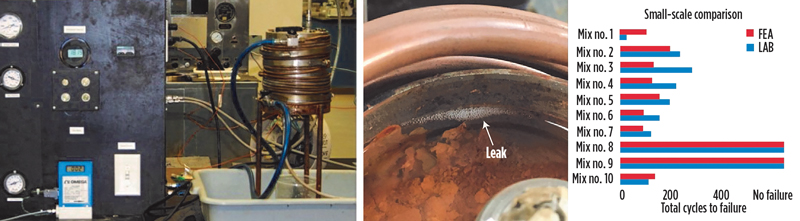
In the example shown in Fig. 1, a test sample is subjected to temperature variations through repeated heating and cooling cycles while it is pressurized from below. This process is repeated until gas bubbles appear at the top of the test sample, indicating that a failure of the barrier has occurred. At the same time, an FEA model replicates the same test sequence, and the results are compared. In the example, gas bubbles appear at the interface between the casing and cement. The FEA indicated the same failure mode. The number of cycles to failure also can be compared between test and FEA, where an excellent match can be achieved.
Step 3 - Large-scale testing. Further validation of the FEA is then achieved through full-scale testing, where samples of the true-size well casings are subjected to similar testing, and again the FEA is used to replicate the test. The comparison between the test and FEA is again very good.
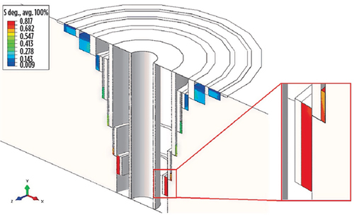
Step 4 - FEA of the well. The final stage is modeling the well in its entirety to determine whether the cement barriers will survive the loading over the well life, Fig. 3.
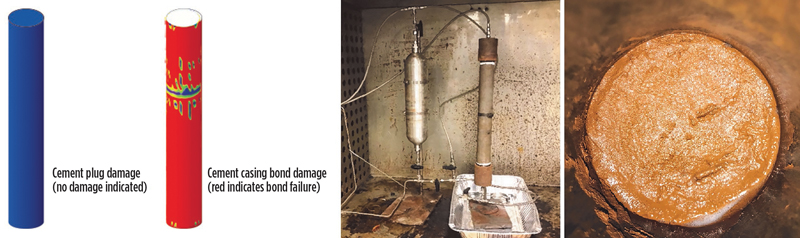
A further use of the FEA is to perform forensic studies to explain why a barrier has failed. In the example shown in Fig. 4, a temporary cement plug failed to hold pressure in the well. A forensic analysis was performed, following similar principles to the multi-step procedure already outlined. A test sample was subjected to temperature and pressure cycles in an oven until bubbles were observed at the cement casing interface. The FEA was then used to calculate the damage to the cement plug and the cement-casing bond. The FEA showed no damage to the cement plug itself but correctly predicted that the cement-casing bond had failed. The FEA was then used to find an alternative cement design that would be effective where the initial design was not.
Simulation enhanced thermosetting resin engineering. Resin, or to give it its correct name, Thermosetting Polymer, is increasingly being used to enhance the barrier systems in oil wells. They offer enhanced material properties that make them an attractive supplement to cement, when conditions in the well demand it. Resin can have significantly higher tensile and compressive strengths, low elastic modulus, which helps limit the tensile stresses acting across the resin-cement bond and also exhibits significantly greater bond strengths than cement. The resin is also unaffected by some of the well fluids that degrade cement over time, making resin a long-lasting barrier.

However, there are also certain properties of resin that need to be properly understood to make best use of the enhanced mechanical properties. Thermosetting polymers produce an exothermic reaction as they cure, meaning that they generate heat. If not properly controlled, this can make the resin expand. Resin also has a much higher coefficient of thermal expansion than either steel or cement, exaggerating that expansion relative to its surroundings. If the resin begins to set while it is in a hot expanded state, when it begins to cool, the shrinking of the resin will tend to develop tensile stresses between the resin and the steel casing. This can lead to failure of the resin-casing bond, Fig. 5.
Wild Well’s engineering team has been utilizing CFD to simulate the resin curing process, so that the curing time can be predicted. The resin chemistry can then be engineered, using a patented process to ensure that the resin sets well after the peak temperature occurs, minimizing any shrinkage effects.
In a similar way to the step-by-step validation process described for cement, the CFD also needs a good characterization of the resin. The first stage is a simple resin curing test, where a small 1-lb mass of resin is cured in a thermos flask and its temperature recorded. These tests are quick and cheap to perform. The temperature information from this simple test is then used to calibrate the polymerization mechanism within the CFD simulation.
Once the CFD is calibrated, it can then be used to predict the temperature during curing in larger-scale tests, or, most importantly, in the well conditions the resin will experience. The CFD results can be compared to a physical test. In one physical test used, a 5-gal bucket of resin was cured while submerged in a temperature-controlled water bath. While the CFD temperature prediction is not a perfect match for the test, it does predict the timing of the peak temperature quite well. This is the key information needed for the design team to adjust the resin chemistry, so that curing occurs well after the temperature and, hence, expansion peak occurs.
CLOSING REMARKS
Advances in simulation technology have allowed designers to better understand how barrier materials will respond to the loading they are exposed to over the life of the well. This enables more robust barrier solutions to be developed, leading to a reduction in barrier failure and fewer well control incidents. It is also important to emphasize that a key aspect of making best use of that technology is a thorough validation process, where the materials are characterized correctly and the simulation results, whether FEA or CFD, are compared against test results.

- Managed pressure drilling to manage pressure wells: Managed pressure unlocks offshore success (October 2025)
- Smarter well interventions accelerate productivity (July 2025)
- Harbour Energy successfully appraises Kan discovery in Mexico, increases estimate to 500 MMbbl of oil-in-place (June 2025)
- Drillships in the digital age: Capturing new opportunities for smarter, safer and more sustainable operations—at any age (April 2025)
- Unlocking the full potential of custom HPUs in offshore drilling (April 2025)
- Drilling rig innovations: In the line of fire, knowledge is power (December 2024)
- Subsea technology- Corrosion monitoring: From failure to success (February 2024)
- Applying ultra-deep LWD resistivity technology successfully in a SAGD operation (May 2019)
- Adoption of wireless intelligent completions advances (May 2019)
- Majors double down as takeaway crunch eases (April 2019)
- What’s new in well logging and formation evaluation (April 2019)
- Qualification of a 20,000-psi subsea BOP: A collaborative approach (February 2019)

