Making hole in a digital world
This year’s review of drilling rig innovations polled seven companies and produced insights across a broad landscape. The following is an industry snapshot of advances in digital well construction; automation of drilling; MPD; casing makeup; wellhead and BOP design; and finally, shale-specific rig design.
DIGITAL WELL CONSTRUCTION
Well construction is a complex, costly process. Additionally, the processes, themselves, can be outdated, resulting in multiple procedures and excessive paperwork. This can leave engineers struggling to find the right information quickly and effectively.

Schlumberger says these factors are limiting the quality of wells being planned and the numbers of wells drilled, and are consequently barriers to efficiency and potentially safety. To address these limits, the company recently launched its DrillPlan digital well planning solution as the first step in an integrated well construction workflow, Fig. 1.
Drilling a well involves multiple teams performing various jobs at different points in the well construction cycle. By putting a single source of real-time data on the rig, and a single, digital plan, more data can be processed, resulting in better-informed decisions.
This automation of routine processes frees up rig crews and allows the wider team to focus on the physics and science of drilling, rather than its administration. This connecting people and data results in more agile workflows, ultimately optimizing drilling performance.
Schlumberger’s solution describes a cognitive drilling rig that combines advanced mechanization with drilling automation applications. Importantly, “science-infused” software supports the digital operation of this mechanized rig by connecting the physical and digital worlds—effectively uniting subsurface knowledge with surface operations.
The DrillPlan digital well construction solution, launched at the SIS Global Forum in September, enhances user collaboration and provides a new way of working for drilling teams by transforming the planning process. Operators and service companies have access to essentially all data and science needed in a single, common system—creating a circular workflow where plans are improved as new data are added. This enables future drilling at these companies to benefit from prior experience.
The solution ultimately will deliver a digital plan for execution by the wellsite system, with the goal of ensuring that the rig is operating at peak performance. Any deviation from the plan will be highlighted, and the best correction decision will be supported, if an unplanned event occurs. The system connects all the wellsite and office teams involved in the drilling operations from the wellsite to the office, from development geologists to drilling and production engineers, to provide access to all offset information and cross-domain expertise.
The company reports that the DrillPlan solution, currently available for North American land operations, has demonstrated both quality and efficiency gains, producing well planning programs in days rather than weeks. Hundreds of plans have been generated in more than a year of field-testing. In West Texas and Canada, seven oil and gas companies evaluated the solution extensively and customized it to their well construction process.
The company also has partnered with UK operator BP to further develop the solution. “Until now, well construction has not been in the spotlight. DrillPlan has the potential to have a quite significant impact on how our engineers spend their time,” said Bernard Looney, BP’s upstream chief executive.
DRILLING AUTOMATION
Drillers are overwhelmed constantly with massive amounts of data and tasks when drilling a well. NOV developed the NOVOS process automation platform to help the driller step back from these complex, repetitive tasks of machine and process control by managing rig equipment to execute drilling programs.
The platform was introduced to the land sector last year and has been used successfully on dozens of rigs in West Texas, Oklahoma, Pennsylvania, Alaska and Canada. NOV plans to test the offshore version this year and implement the offshore NOVOS platform in the first part of 2018.
NOVOS uses an imported well plan to perform operations by following the desired drilling parameter ranges until total depth is reached. The driller oversees the process and can take control if desired. The system, which NOV says can be added to an existing rig in hours, provides a common platform for the control, monitoring, scheduling and optimization of drilling operations.
Since the system is not custom-built, it is scalable and does not require extensive research or redevelopment work for each new deployment. NOVOS can be placed quickly on top of an existing NOV control system, for rapid deployment. The scalable installation enables the system to be deployed easily across rig fleets, which increases overall consistency, enhances fleet performance, and enables the operator and drilling contractor to plan ahead.
NOVOS includes various applications for faster, safer, and more effective drilling. It also can incorporate third-party, customized applications for specific drilling requirements. A software development kit allows developers to create and deploy their own optimization applications to address specific challenges. A group of operators, contractors, and service companies is already creating value-added applications that will be delivered in 2018.
MPD AUTOMATION
In the evolution of the MPD-ready rig, the key enabler will be the ability to efficiently connect specialized equipment and data with the rig system, says AFGlobal. The company’s NControl managed pressure drilling (MPD) platform concept advances this process through seamless integration with the rig and third-party MPD control systems into the driller’s cabin. The company says development of the platform sets the stage for automated MPD, and its growing incorporation as a standard rig feature in the global fleet.
The early foundation for this high-level MPD integration began with the fundamental control achieved with applied surface backpressure. This advance was based on an offline hydraulics model, with the operator setting backpressure and tuning the choke controller to accommodate for changing conditions. The operator also was able to identify well control events.
Today, the state of the art is automated bottomhole pressure (BHP) control. The operator sets BHP for different hole sections. The MPD system then determines choke pressure set points, based on real-time estimates of BHP, using hydraulic model inputs for pressure, temperature and volume. A choke controller makes adjustments to maintain the appropriate backpressure and respond to contingencies. The MPD system alarms for well control events, and the operator takes over if a kick or loss occurs.
This level of performance is the first step in developing the NControl platform. It achieves the critical capability to control and acquire data from individual components. The development of automated choke controls that precisely tailor choke position and flowrates to the specific task is one of the big advances in this area. Another example is AF Global’s active control device (ACD), a replacement for conventional rotating control devices (RCD). The ACD technology is radically different from traditional devices, in that the element does not rotate with the pipe. Instead, it hydraulically applies the closing pressure to seal the wellbore. As a consequence of this active pressure, the system also provides feedback as a positive wear indicator. These pressure data also can contribute to the overall understanding of the health of the system, making conditioned-based monitoring possible.
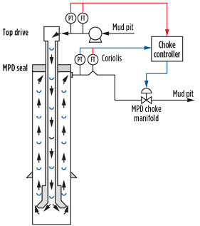
With this control capability established, ongoing NControl platform development is focused on facilitating real-time hydraulic modeling and integration with the choke manifold, Fig. 2. At this level, the MPD system identifies well control events and automatically controls back pressure to offset an event, while contributing data to the overall rig operations.
To support this degree of integration, the platform is a modular, open architecture, with the flexibility to interface seamlessly with various rig control systems and third-party technologies. In this fashion, it provides a scalable path for transitioning from conventional drilling to riser gas handling, to conventional MPD, to automated MPD—as desired by the drilling contractor and operator. Upgradable and expandable software also ensures that the system can grow as rig systems continue to evolve.
CASING MAKEUP AUTOMATION
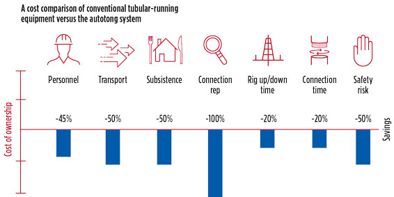
Precise control and error-free evaluation of casing and completion string make-up results in a dependable process that requires fewer personnel and reduces well integrity risks. That’s the objective of Weatherford’s AutoTong system, which it says can reduce offshore costs by approximately 20%, compared to conventional tubular-running equipment, Fig. 3.
Described as the first and only technology to automatically make up casing and completion strings, and autonomously evaluate the connection, the system fully controls make-up to the final torque, once the manual power tong is positioned on the pipe, and the initial spin-in of the connection is completed.
Automated makeup and evaluation yield distinct benefits. Automated makeup enables precise control of the process that is independent of operator influences or other human factors. Autonomous evaluation, using the system’s AutoEvaluate feature, eliminates subjective graphical interpretations. Key capabilities include precise, consistent automated make-up, accurate evaluation, simplified operation, reduced rig-up time, and elimination of manual data entry.
The system controls the make-up procedure with digital precision. For each connection, the system uses a proprietary speed-control algorithm—based on pipe and thread OEM criteria—to automatically slow down when approaching the optimum torque. These speed adjustments eliminate the need for a traditional dump valve and the corresponding sudden stops in the make-up process.
AutoEvaluate software provides built-in connection evaluation that eliminates human errors during connection acceptance verification. The software objectively interprets connections, using 10 times more data points than the human eye can see, which removes gray areas for verified connection integrity. If the software rejects a connection, its troubleshooting advisor application identifies the root cause of the issue and recommends corrective action.
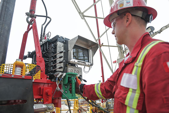
The AutoTong system reduces the knowledge required for operation and makes interaction easy. To initiate the final make-up process, the operator simply pushes a button on the tong’s handgrip; a tablet mounted on the tong displays a torque/turns graph, indicates tong status, and enables data entry as needed, Fig. 4.
The all-in-one system is installed in a single step to reduce time and costs. By comparison, conventional make-up technology involves multiple individual components that require connectivity for both hardware and software communication.
The automated system standardizes data inputs to eliminate erroneous entry that can result in over- and under-torqued pipe, and catastrophic connection failures. For example, the system stores tong data (such as handle length and serial number), identifies components (such as the load cell), and detects shoulder torque.
WELLHEAD DESIGN
When it comes to wellhead installation, time is not only money; it’s rarely on your side. It’s a labor-intensive process in a dangerous environment, where non-productive hours in the rig cellar not only subtract from the bottom line, they put workers and assets in harm’s way.
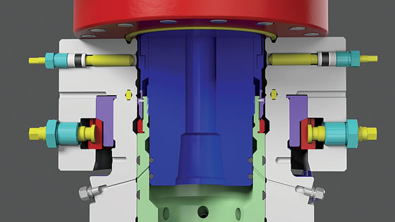
To address these interdependent challenges, Weir engineered a new type of wellhead to reduce overall non-productive time while enhancing safety. Its Seaboard Unitized Lock-Ring wellhead (ULR) design is the product of a collaborative approach involving a multidisciplinary team of engineers, customers, manufacturing, supply chain, and quality assurance experts.
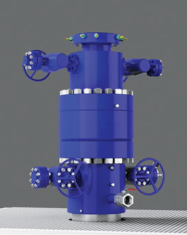
Ultimately, says Weir, the ULR was designed to ease the pressure on an operator’s bottom line, Fig. 5. Collaborating with a diverse team of experts allowed the design process to look beyond traditional variables to deliver a significantly lower cost of ownership.
The expanded team was able to not only address issues of equipment design, but factors such as materials sourcing, which typically don’t figure into the problem-solving process. As a result of leveraging parallel development paths during manufacturing and streamlining logistics, design-to-delivery time was reduced 50%, from six months to about 12 weeks.
The ULR design had to be more compact than the average wellhead to address many traditional wellhead challenges. Creation of a nested system within a single-piece housing resulted in an overall shorter stack-up height and reduced weight that resulted in easier access and lower risk installation, Fig. 6.
Running procedures on traditional wellheads were studied carefully. Normally, BOP removal is required to install the next stage. The BOP is then reconnected, with each flange taking 3 to 4 hr. The process also must wait on cement to set before lifting the BOP off the next wellhead, manually setting slips, and trimming casing to match the next spool. This procedure can take up to 18 hr.
Not only is the typical running procedure time-consuming, it’s a dangerous process involving flame cutting, welding, and grinding in a volatile environment. A key design goal was to simplify installation by eliminating these time-consuming procedures, and their attendant risks and costs.
The ULR’s mandrel casing hangers allow casing to be run, landed, circulated and cemented through the rotary table and BOP with no cutting, welding or grinding required. An internal lock-down seal assembly vastly simplifies the procedure while eliminating the multiple leak paths found on traditional wellheads. Combined, these improvements can save 6 to 8 hr per casing string.
A quick-connect hub lets the operator align, land and secure the BOP on the wellhead, much faster than with a conventional connection, reducing rig-up time from 2 hr to less than 30 min.—with no waiting on cement before resuming operations.
BOP DESIGN
Conventional blowout preventer (BOP) design is challenged on multiple levels. Among them are the growing operational requirements posed by drilling applications, the introduction of new regulations and standards, and marketplace demand for greater cost efficiency. These factors can limit the application, effectiveness and economics of standard BOP technology, says AXON Pressure Products.
The company’s X-TREME BOP design offers an innovative approach to dealing with these issues, Fig. 7. While conventional multi-cavity ram BOPs have just two or more cavities in a linear arrangement, the AXON design arranges ram cavities in a staggered pattern. Staggering the ram cavities arranges them in closer proximity to each other along the wellbore. In double, triple and quad configurations, the unique pattern allows additional shearing rams at little-to-no extra cost versus conventional units.
AXON says the design addresses many conventional BOP limitations. Greater drilling demands and new industry standards, such as requirements for dedicated shears, can result in BOP stacks exceeding the capacity of standard handling equipment. The staggered X-TREME BOP design addresses this with a substantial decrease in height and weight.
The staggered arrangement also allows for simultaneous maintenance on multiple cavities and easier access to internal components. Service life is improved, due to reduced body stress achieved with more supporting materials between cavities, along with decreased bending stresses, due to reduced height.
Shearing safety and performance is improved by the offset cavities, which provide concurrent and/or subsequent activations at alternate angles. The different shearing directions provide guidance for better drill pipe centering.
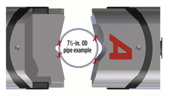
In addition, the new BOP design features four-point-contact V-Shear technology that creates high stress in localized areas to initiate crack propagation and/or pipe shearing at lower operational pressures, Fig. 8. This pipe centering technology produces a higher shear force and lower operating force to enhance shearing on a variety of pipe sizes.
SHALE RIG
Shale well construction costs and operational demands in North America continue to drive land rig design. Long laterals, batch drilling and other shale development practices have resulted in a host of performance demands that impact rig hoisting, rotating and circulating systems. The multi-faceted design response includes innovations aimed at hole cleaning, trip time, penetration rates, and move times, along with more sophisticated data management systems, all in the name of greater efficiencies.
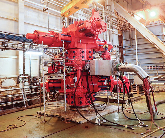
One of the latest and most specific innovations is Drillmec’s Striker-800 design, an ultra-high-spec rig package engineered for shale batch and cluster drilling operations, (see cover image). Drillmec says the design is the first off-the-shelf turnkey shale-drilling package to flexibly integrate all rig components. The modular design allows the drilling contractor to choose the top drive, drawworks, mud pumps, and other drilling equipment from various manufacturers, including Drillmec. This flexibility enables rig specifications to be cost-effectively matched to the existing fleet, as well as specific application requirements. The modular design also provides fast integration of third-party services, such as cement, mud, and waste management.
The “ultra” designation denotes an emphasis on the application analysis that was performed prior to developing and finalizing the package, and the related technological offering. The upfront, shale-oriented analysis resulted in multiple features and specifications aimed at safely reducing rig-up and moving time; improving cluster and batch drilling performance; development of specific data management systems; and enhancing efficiency and reliability within a simple, space-efficient layout.
Rig-up, moving, safety and speed are emphasized with a patent-pending Hydraulic Safe-Lift raising system that enables mast and setback installation at ground level, and erection in a single “one-shot” operation. BOP handling efficiency and safety is enhanced with a fully covered test-stump work area that facilitates offline maintenance and testing for two BOP stacks.
Rig walking during multi-well pad drilling, especially in high-density fields, benefits from several features. A side cellar substructure provides the clearance to walk the rig over existing wellheads and cellars with different spacing, using a multi-directional walking system. Two walking configurations provide versatility in different well cluster grids and allow the rig to cover 150 ft (expandable to 250 ft) in walking distance length and 50 ft in width for a three-cluster well
row configuration.
The built-in rig module is designed to reduce the release-to-spud time between wells. It includes a floor-mounted choke manifold, choke and kill lines, accumulator unit and control lines to minimize BOP and pressure testing time. In addition, the trip tank and treatment tank are onboard to enable real batch drilling capability. The rig can walk with a full set-back, hung BOP, and a treatment tank full of mud to further enable economic batch drilling operations. A hybrid cable management system allows X- and Y-axis skidding without power shutdown.
Standard specifications for the rig include a 137-ft clear height, 800,000-lb static hook load mast on a 32-ft drill floor with a 600,000-lb setback capacity. Hoisting is achieved with a 1,500-hp drawworks, and rotation is provided by a 500-ton high-torque top drive. The high-pressure mud system includes heavy-duty 1,600-hp mud pumps with 7,500-psi working pressure. ![]()
- Applying ultra-deep LWD resistivity technology successfully in a SAGD operation (May 2019)
- Adoption of wireless intelligent completions advances (May 2019)
- Majors double down as takeaway crunch eases (April 2019)
- What’s new in well logging and formation evaluation (April 2019)
- Qualification of a 20,000-psi subsea BOP: A collaborative approach (February 2019)
- ConocoPhillips’ Greg Leveille sees rapid trajectory of technical advancement continuing (February 2019)

