Large-diameter completion string saves time on landing and intervention operations
To allow for clearance of the wellhead crown plug and installation of completion components, tubulars for completion landing strings and intervention pipe in deepwater operations must provide a large internal drift (ID) diameter. Currently available strings have proven insufficient for running and retrieval of wellhead crown plugs on many large ID subsea trees; standard 6⅝-in. pipe only allows a maximum drift diameter of 5½ in., requiring operators to use casing tubulars on trees with larger crown plugs, which are more difficult to use.
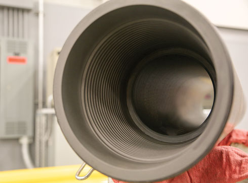
To address this shortcoming, National Oilwell Varco (NOV) developed a completion landing string (CLS) using 7⅝-in. pipe and a built-for-purpose, gas-tight, large-drift, pressure-rated, rotary-shouldered connection, Fig. 1. To be compatible with the iron roughnecks and pipe-handling equipment deployed on Gulf of Mexico (GOM) rigs, the new connection optimizes OD and makeup torque.
IMPLEMENTATION WITH SUBSEA TREES
The type of subsea production tree used in offshore operations plays an important role in determining string specifications. Differences in crown plug diameter between vertical and horizontal subsea production trees, for example, impact the size of the CLS or intervention string. Subsea vertical trees have a dual-bore configuration, with crown plugs for both the annulus and production bores. Conversely, horizontal subsea trees incorporate the annulus, which is controlled by gate valves instead of plugs, into the body of the tree. The crown plug in such a monobore design has a larger diameter than those found in vertical subsea trees, requiring a CLS or intervention string with a larger drift diameter (up to 6⅛ in.).
Advantages of the new CLS. The horizontal subsea trees’ larger-diameter crown plugs demand a larger drift diameter than is available on a standard 6⅝-in. CLS. This shortcoming has meant that premium casing must be used frequently for landing subsea completions, when the necessary drift diameter exceeds 5½ in. Premium casing provides a gas-tight, metal-to-metal seal connection and the larger drift diameter needed to pass larger crown plugs. But this also increases deployment time, requires casing running crews, and incurs higher repair costs. Premium casing has, until now, been the only option that could be used in such operations, but the development of the 7⅝-in. CLS changes this, providing distinct advantages in the field.
Normal rig-up and pipe-running procedures are maintained with the new CLS, and standard mechanized pipe-handling systems, elevators, iron roughnecks, and slips can still be used. The robustness of the rotary-shouldered connection ensures that connections can be made up and broken out several times without damage or loss of performance, while casing connections are designed for a minimum number of make-ups and can have high repair costs. The new CLS also eliminates the need for premium connection technicians and torque-monitoring equipment and personnel. The reduction of people active on the rig floor increases operational safety, resulting in fewer HSE accidents. Operationally, savings are realized from faster make-up, using the new connection technology in the CLS.
STRING DESIGN AND CONNECTION DEVELOPMENT
To efficiently solve the evolving subsea completion challenges, a CLS was required with a 7-⅝ in. OD tube body to increase the drift diameter to a minimum of 6⅛ in. An external upset design was incorporated to maximize the tool joint’s ID while providing the required weld area. A maximum make-up torque of 100,000 ft/lb, and a maximum tool joint OD of 9¾ in., were required to be within the capability of typical
iron roughnecks.
Additionally, the connection had to have a minimum internal pressure rating of 20,000 psi, combined with a minimum external pressure rating of 10,000 psi, with the tube body pressure rating equal to, or in excess of, the connection pressure rating. This was achieved by using pipe with a wall thickness of .625 in. and a specified minimum yield strength of 150 ksi. Range 3 joints also were required to reduce the number of connection make-ups/break-outs, and to provide cost savings from reduced run times, as compared to Range 2 strings.
The objective was to create the largest pressure-rated, gas-tight, rotary-shouldered connection for a 7⅝-in. completion tubular. A proven radial metal-to-metal seal technology, which provides necessary pressure ratings, was combined with an optimized connection geometry (taper, pitch, thread height, ID chamfer), to ensure relatively low make-up torque for such a large connection, meeting the connection’s design requirements. The primary seal is the radial metal-to-metal seal on the pin nose, and the external shoulder provides the secondary seal.
The internal shoulder, which is not considered a pressure seal, acts as a torque stop to enable the pipe to be racked back on the pin nose during tripping operations without damaging the sealing area. It was important to optimize interference, which is a critical parameter of the radial metal-to-metal seal’s effectiveness, to ensure adequate contact stresses at the sealing surfaces. Excessive interference potentially leads to galling, while insufficient interference inhibits the connection’s ability to seal.
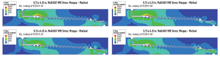
Validation testing. During the development process, engineers employed finite element analyses (FEA) to verify stress distribution in the connection and optimize radial seal interference, Fig. 2. Two-dimensional axisymmetric models of the connection were generated, and nonlinear stress-strain curve data, representing a specified minimum yield strength of 130,000 psi for material properties, were used to simulate elastoplastic behavior.
Imposing interferences at the shoulders and radial seal allow for simulation of applied make-up torque, assuming a friction coefficient of 0.08 at contact surfaces throughout the analysis. FEA results verified the selected dimensions and tolerances provided stress states that were comfortably within the material capabilities under the loading bound by the connection operating envelope.
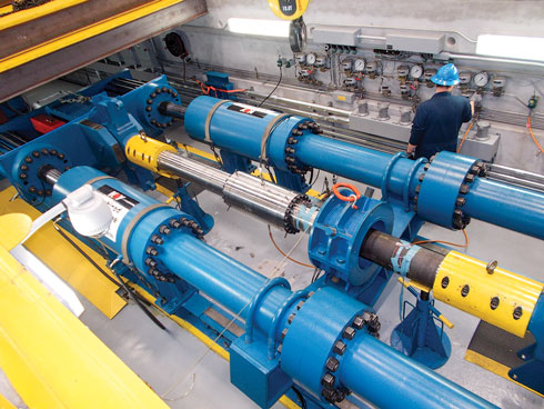
Full-scale simulation. It was determined that comprehensive, full-scale physical testing of the new connection was necessary to verify that it would perform as intended. A two-phase testing program was developed, using API methodologies, to address this need, Fig. 3. The first phase involved galling resistance (make and break) testing, which subjected the connection samples to multiple make-up and break-out cycles, to assess the connection’s durability. The second phase involved sealability testing, which subjected the same connection samples to a range of combined loading conditions, including elevated temperature, axial tension and compression loads, and internal and external pressures.
The sample connections passed the make-and-break test successfully, with break-out torque correlating closely with theoretical values. There was no visible galling on the shoulders, threads, or radial metal-to-metal seal. Additionally, no leaks were observed during any of the tests, and the samples completed the sealability combined load testing successfully, which verified the connection’s internal and external pressure ratings at 20,000 and 10,000 psi, respectively.
FIELD TEST/LIVE WELL APPLICATION
A field trial and qualification of the 7⅝-in. CLS tubular were conducted in May 2016 aboard an ultra-deepwater drillship. The purpose of the qualification was to assure compatibility of the new, larger-sized tubular with the drillship’s pipe handling and running equipment, and to validate the connection’s make-up and break-out performance under field conditions. Personnel from the operator, the drilling contractor, a rental company, and the manufacturer were in attendance.
The 7⅝-in. CLS tubulars have a specified drift of 6⅛ in. The pipe was drifted with a 6.076-in. diameter drift. The subsea tree’s lower crown plug had a 5.2-in. OD, and the upper crown plug has a 5.781-in. OD. Make-ups and break-outs were conducted with an iron roughneck that had a rated capacity of 100,000 ft/lb make-up and 120,000 ft/lb break-out. The iron roughneck provided clearance for the 9¾-in. OD tool joints. Make-up and break-out torque values were acceptable, and the rig’s iron roughneck was determined to be capable.
Using the rig’s pipe-handling system, there were no issues observed with the drillship’s pipe-laydown system and pipe-running system, nor their ability to properly transport and handle the 7⅝-in. CLS tubulars. To ensure proper fit into the rig’s vertical tubular racking system, the two stands were racked back in both side-by-side and piggy-back orientations. The team encountered no issues during the test, and tool joint and tube ODs were compatible with the tubular racking system. The necessary crossovers, pup joints, inside BOP valves, safety valves, and lift caps were manufactured for use with the 7⅝-in. CLS.
Deployment. The 7⅝-in. CLS has been deployed on four completions in the GOM. The strings were picked up and racked back with conventional rig handling equipment, since tubular running services were not required. This enabled crews to pick up and rack back stands between multiple other operations, and utilize rig flat time when available. The additional costs associated with using casing, tubular running services, and related equipment were avoided. When requested by the operator, the manufacturer and rental company provided a representative onboard to train the rig crew and assist in picking up the CLS and racking back. The rig crew, manufacturer field services, and rental company quality assurance developed a solid care and handling procedure.
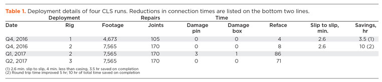
The rig crew was pleased with the ease of running the 7⅝-in. CLS, and became more comfortable and efficient in running the CLS as they gained experience. The connections made up easily, and no noticeable issues were observed. Both the operator and the drilling contractor agreed that the new string ran quicker and safer than the previous casing landing string. The connection time was reduced by a minimum of 4 min. per connection, slip to slip, in comparison to the previous premium casing connection landing string, resulting in approximately 3.5 to 10 hr of time savings running the completion, Table 1.
CONCLUSION
The 7⅝-in. CLS was successfully developed, performance tested and deployed. This first large-diameter, purpose-built, gas-tight completion and intervention tubular provides 6⅛-in. internal drift diameter, new connection technology, and is compatible with the iron roughnecks and pipe-handling equipment on current GOM rigs.
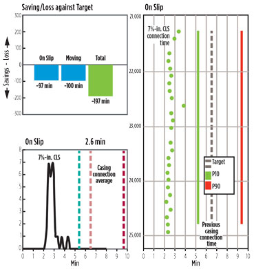
Requiring only the rig’s conventional pipe make-up and handling equipment, and no specialized equipment or additional personnel, flat time was utilized to make up and rack back stands, increasing overall rig efficiency. The string ran approximately 4 min./joint faster, slip to slip, than the previously used premium connection casing landing strings, Fig. 4. The string was run in hole safely, with the umbilical using the tubular running services’ slips and personnel, and the trip out of hole was safe and efficient.
Plans going forward. Based on these successful deployments in the GOM, other operators are considering adopting this technology in the region and in other parts of the world. Major service companies are also considering including it in their offerings for well completion and intervention. In addition to large drift diameter completion applications, the development of 7⅝-in. rotary-shouldered pipe will enable high-capacity drilling landing strings, with capacities approaching 4 million lb. NOV also has qualified the processes necessary to offer a variation of the 7⅝-in. product with a thicker section of tube below the box tool joint to resist slip-crushing under such high tensile loads. Ultimately, 7⅝-in. drill pipe will become an enabling technology for future ultra-deep and ultra-extended reach wells. ![]()
- Applying ultra-deep LWD resistivity technology successfully in a SAGD operation (May 2019)
- Adoption of wireless intelligent completions advances (May 2019)
- Majors double down as takeaway crunch eases (April 2019)
- What’s new in well logging and formation evaluation (April 2019)
- Qualification of a 20,000-psi subsea BOP: A collaborative approach (February 2019)
- ConocoPhillips’ Greg Leveille sees rapid trajectory of technical advancement continuing (February 2019)

