Offshore advances address drilling and production, as well as data
The majority of our 2017 collection of new technologies and next-generation improvements on existing products is almost split evenly between drilling and production applications, with several items pertaining to completions. One of the interesting trends that has shown up in this year’s grouping is that about a third of the items feature some form of data generation or collection, as the industry becomes increasingly involved in data analytics and digital transformation. Driving much of the innovation is the industry’s ongoing need to save time and money. ![]()
NEW AC DRIVE CUTS ENERGY COSTS, IMPROVES RELIABILITY
Rockwell Automation has launched a new drive solution that will help operators reduce energy costs and increase machine uptime for assets running in high-demand applications.
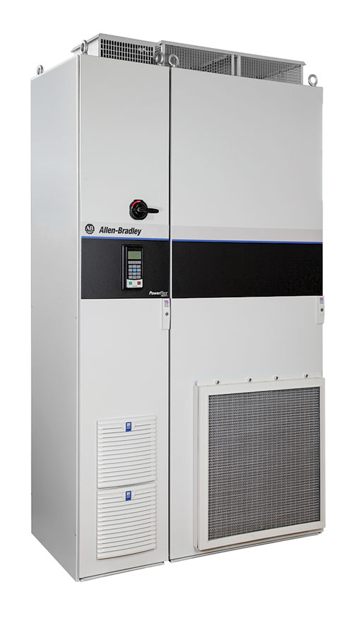
The Allen-Bradley PowerFlex 755T drive (Fig. 1) provides a low-harmonic, active front-end structure that helps reduce problems in power distribution lines. It also offers a high-performance, variable-speed control that’s well-suited for top drives, mud pumps and drawworks, which provides precise motor control in a compact footprint. In addition, there are common-bus system configurations, reducing the number of components required and minimizing the footprint for applications like multi-well pad operations, where several drives can be housed in a central location. There also are predictive diagnostics to estimate and provide notification of the remaining lifespasn of drive components.
Additionally, the offering of this drive marks the introduction of TotalFORCE technology from Rockwell Automation, delivering excellent motor control through precise, adaptive control of velocity, torque and position. The 755TL drive uses active, front-end technology and an internal harmonic filter to reduce harmonic distortion. This version delivers power from 250 to 1,800 Hp (160 to 1,400 kW). The 755TR model delivers power from 250 to 3,000 Hp (160 to 2,300 kW), and includes both regenerative and harmonic mitigation solutions. This drive helps reduce energy consumption and costs by delivering energy back to the incoming supply, resulting in a more efficient solution.
Finally, the 755TM drive allows users to build the system that best fits their needs for regeneration and coordination of multiple motors in common-bus configurations. To optimize their system requirements and meet power-consumption needs, users can select from a series of predesigned modules, with a power range from 250 to 3,000 Hp (160 to 2,300 kW).
The combination of low harmonic active front-end structure, high-performance control, and the ability to share a common DC bus structure to reduce footprint, make the PowerFlex 755T drive well-suited for applications like drilling rigs, pumping applications, artificial lift systems and multi-well pad operations.
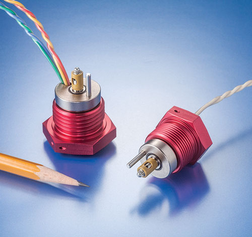
TWO-WAY SOLENOID VALVE
The Lee Company’s new two-way piloting solenoid valve (Fig. 2) provides a simplified flow path for applications requiring only two ports. This two-position, two-way miniature valve features Lee’s unique multi-seal technology, which radically simplifies port layout, offers significant space savings, reduces machining costs and provides superior reliability over traditional sealing methods.
This new two-way piloting solenoid valve is available biased either normally open or closed, and with lead wires or integral electrical connector. Weighing only 0.14 lb, this single coil valve consumes just 7.8 watts at 28 Vdc.
FLOW IMAGING, INSPECTION TOOLS SUPPORT ASSESSMENT OF WELL INTEGRITY
Accurate diagnostics are critical to staying on budget and on time. Halliburton’s Acoustic Conformance Xaminer (ACX) and Electromagnetic Pipe Xaminer V (EPX) services help find leaks quickly. They also help to describe the extent of the damaged pipe that needs to be fixed, leading to an efficient solution for repairing the problem.
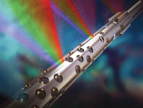
Halliburton has created the first flow imaging tool, the ACX, which locates and images flows behind pipe(s). This technology is used primarily for flow assurance, well integrity and well leaks. It can map flow around the wellbore, including in-between annuli and throughout the completion.
The ACX tool measures acoustic energy with an array of highly sensitive sensors, allowing detailed, descriptive information about a leak to be collected from several angles. These sensors use a proprietary beam-forming algorithm to define a leak’s radial distance and depth location in real time, Fig. 3. The service is run continuously (up to 25 ft/min.) to capture all data throughout the well or problem area.
When corrosion is a problem, the new EPX V pipe inspection tool quantifies metal loss in one to five concentric strings of pipe in a wellbore, using accurate, high-definition frequency (HDF) technology. It allows customers to examine the whole well in one trip and assess pipe condition.
The EPX V tool has an outside diameter of 1–11⁄16 in. and operates by inducing HDF electromagnetic energy into the surrounding pipe, which propagates through the concentric well strings with no wellbore fluid influences. The interaction with the metal of the pipe returns signals to the tool, yielding information about the state of metal loss in each pipe.
Used together, these two technologies have proven to be valuable resources in well integrity issues.
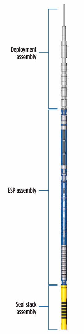
BAKER HUGHES TRANSCOIL ESP SYSTEM DESIGNED FOR RIG-LESS DEPLOYMENT
The new Baker Hughes TransCoil rig-less-deployed electrical submersible pumping (ESP) system was developed to help operators bring wells on production faster and lower the costs associated with installing and replacing ESPs, Fig. 4. By eliminating the need for a rig in fields where availability is a concern, or where high intervention costs can limit artificial lift options, operators can minimize deferred production and lower overall lifting costs to extend the economic lives of their assets.
The system—developed in participation with Saudi Aramco—is an inverted ESP system with the motor connected directly to a new, proprietary power cable configuration. This eliminates the traditional ESP power-cable-to-motor connection, to improve overall system reliability. There is no in-well “wet connection,” as in wireline-deployed ESPs, and thus, no need for a rig to pull the tubing and replace the wet connection if it fails. Additionally, because the system can be installed through a deviation in the wellbore, operators can land the ESP closer to the producing zone for greater reservoir pressure drawdown and reserve recovery.
The power cable design enhances the reliability of the deployment string, compared to traditional coiled tubing (CT)-deployed ESPs that simply pull the power cable through the CT. The design also extends the system operating range to 12,000 ft, versus approximately 7,000 ft for traditional CT-deployed ESP systems, because the weight of the power cable causes it to collapse inside the CT at greater depths, creating an electrical failure.
The TransCoil system can be installed in a 4½-in. to 9-in. casing, in wells with flowrates up to 18,000 bopd. In mature offshore fields, where high intervention costs can limit ESP applications, the system can be deployed through the existing 4½-in. tubing, saving the time and money required to pull the existing completion.
One of these systems was installed recently and commissioned in Saudi Aramco’s Khurais field. Rig-based work to replace the completion was completed ahead of the rig-less operations. The system was installed at 4,900 ft in 7-in. tubing. The first rig-less operation reduced installation time nearly 50% over a rig-based installation and it was fitted with a vertical wellhead. Further deployment efficiency improvements are expected in the future.
NEXT-GENERATION SOLID EXPANDABLE
SameDrift is Enventure’s next-generation solid expandable, Fig. 5. Building on years of industry-proven experience, the SameDrift Openhole liners can be installed in the wellbore without loss of internal diameter (ID), providing the same drift as the casing string above the expanded liner. The benefits of having successive casing strings with equal drift diameter is larger ID at total depth (TD), improved cementing for the next casing string, the enabling of drilling deeper wells, isolating trouble zones, completing the well earlier, starting production sooner, and increasing output rates.
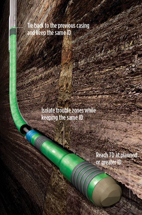
This solid expandable is modular, so it can be stored onsite for quick use in both open-hole liners and open-hole clad installations. Expanding the open-hole liner only requires the operator to plan for a shoe receptacle.
Once the expandable is lowered into place and cemented, or clad, into place, it can be rotated to improve cementing and overall wellbore integrity. Expansion takes only one trip, which lowers non-productive time (NPT). Building on the firm’s SET technology, SameDrift enables the liner to reciprocate or rotate, to get around ledges, cuttings or other obstacles. This helps to ensure faster installation. Using CLEAR cone technology, this unique expansion process enables the same diameter to be maintained.
With proper planning, multiple liners can be installed, end-to-end. Since the same diameter is maintained throughout, drilling equipment can be standardized, streamlining drilling and reducing cost.
The expandable can be used in isolating multiple trouble zones without reducing the diameter after each clad. When a loss zone is encountered, the existing drillstring only needs to ream out the troubled formation. This, in turn, enables a clad installation through a previous clad while keeping the current drift. Maintaining the same drift means that one can reach TD at a larger diameter, enabling higher production rates and the ability to drill deeper or even sidetrack into other reserves. This, alone, can save millions of dollars. And because it’s a solid expandable, it isolates formation damage the right way, the first time, requiring less NPT when conventional solutions fail.
ULTRA HIGH-TEMPERATURE LWD
Weatherford’s HeatWave Extreme (HEX) service provides logging-while-drilling (LWD) data in temperatures up to 392°F and pressures up to 30,000 psi. This service (Fig. 6) reliably acquires gamma ray, resistivity, neutron porosity, and density data at high temperatures without wireline runs, extra trips, or temperature mitigation.
Weatherford and a major E&P company jointly designed this technology for HPHT wells in the Gulf of Thailand. Previously existing LWD technology requires extensive temperature-mitigation measures that can result in additional operating time and expense during drilling. To eliminate the need for cooling trips, each HEX component was redesigned for reliability at ultra-HT and vibration environments.
LWD base system. In Phase 1, the team developed the LWD base system. This included a directional measurement sensor that uses orthogonally mounted triaxial accelerometers and magnetometers to provide directional survey measurements.
For bore and annular-pressure measurements, quartz transducers provide data that determine equivalent circulating density. Radially mounted Geiger Mueller tubes provide real-time and recorded gamma ray data to provide lithological information. Phase 1 concluded with neutron porosity measurements. The team developed HT electronics to control He3 neutron detectors, which respond to the rate at which high-energy neutrons are slowed and captured in the formation. This is related to the amount of pore space in the rock, and whether those pores are filled with water, oil or gas.
Resistivity/density systems. In Phase 2, the development team created a fully-compensated, dual-frequency, resistivity tool. Operating at 2 MHz and 400 KHz, the tool provides a range of curves with differing depths of investigation and vertical resolution. The density tool uses HT scintillation detectors with associated electronics to measure the bulk density of the formation.
The development also included a preventive maintenance program that tracks temperature and vibration rates and adjusts maintenance schedules accordingly. The result is an LWD string that can survive 200 hr of operation at 392°F and 4 hr at 410°F without temperature mitigation, dramatically reducing NPT and the cost of drilling in ultra-HPHT environments.
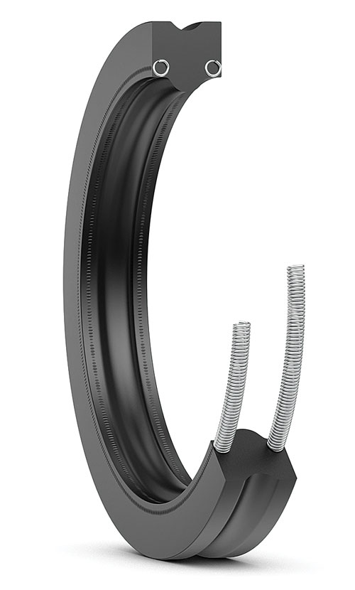
LATEST WELLHEAD SEALS ADDRESS HPHT NEEDS
SKF is releasing a new range of spring-energized, moulded products that complements its current range of machined seals for wellhead applications, Fig. 7. The new product range is the result of an extensive, in-house product development program, with verification and validation in accordance with recognized NORSOK M710 and API 6A Annex F standards.
The third-party-certified elastomers developed by SKF for these seals have undergone sour service aging and rapid gas decompression to the NORSOK M710 standard. The seal designs are verified and validated to API 6A F1.13 FF/HH and F1.11 PR2 qualification requirements.
SKF's objective with this newly standardized offering is to provide well service companies and wellhead manufacturers with a reliable, responsive delivery service. In addition, the goal is to provide robust, competitively priced products of repeatable specification and consistent quality, which are less prone to damage during installation.
With this release, SKF also reintroduces its Locking T-seal for the wellhead market. This seal design, originally developed for the fluid power sector, where it successfully prevents piston seals in large bore cylinders from becoming displaced or misaligned during installation, has now been adapted to the needs of the upstream oil sector.
The Locking T-seal features specially designed retention ridges that snap into place on installation, mechanically locking the anti-extrusion backup rings into the correct orientation and helping to prevent rotation or displacement. The locking action makes seal installation quick and simple, without risking damage to the seal or other system components, while providing a secure connection.
The product is especially useful for difficult-to-access wellhead applications that make use of traditional T-seals, and where it is difficult to retain backup rings during installation. SKF’s Locking T-seals are fully, dimensionally interchangeable with traditional T- or S- (GS-) seals and are, therefore, a viable and proven product option for well service operators.
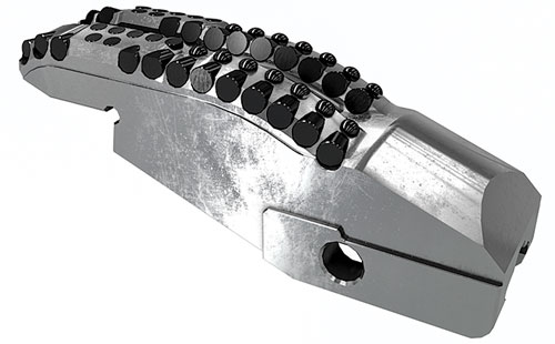
BAKER HUGHES LAUNCHES NEW AUTOMATED TERRADAPT DRILL BIT
Baker Hughes recently launched its TerrAdapt adaptive drill bit, which uses automation to mitigate downhole dysfunctions that cause inefficient drilling and tool failures, Fig. 8.
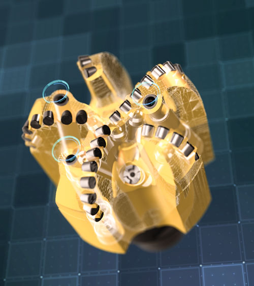
The TerrAdapt bit incorporates self-adjusting depth-of-cut (DOC) elements that extend autonomously to create an optimal DOC, based on the formation to prevent vibrations and stick-slip when the bit transitions between rock types or sections. When the risk of stick-slip has passed, the elements retract, enabling drilling to resume at a maximum ROP. The elements also absorb any sudden shock to the bit face, significantly reducing damage to the TerrAdapt bit’s cutters and other BHA hardware and electronics.
The vast majority of well intervals are drilled through a variety of formations containing layers of different rock types, however, current polycrystalline diamond compact (PDC) drill bit designs feature a fixed DOC control setting that is optimized for only a single rock type. A fixed-DOC bit will drill smoothly in some areas but will perform erratically and inefficiently in others. This is because of vibrations that occur when the bit transitions between different rock types, causing stick-slip.
During stick-slip events, the bit’s bite becomes too aggressive, causing it to “stick” and stop rotating, while the drill-pipe behind it continues to wind up like a spring until the bit releases, or “slips,” and begins spinning uncontrollably. These stick-slip events dramatically increase drilling costs by reducing ROP, and can seriously damage the bit and other expensive mechanical and electrical BHA components. When this happens, operators have to make extra trips to replace the bit/BHA, or continue to drill with diminished performance.
In the Delaware basin, this bit recently demonstrated its value by increasing a customer’s ROP by 27%, compared to the average ROP on offset wells drilled through the same interbedded formations. The bit reduced torque variations 90%, indicating dramatically reduced stick-slip. This enabled the operator to drill 713 ft, or 27%, farther and use significantly less energy than on nearby wells drilled with traditional PDC bits.
This bit is the first in a new line of adaptive bits that Baker Hughes is developing to help operators address various drilling dysfunctions, improve performance, and reduce costs.
NEW CUTTER TECHNOLOGY IMPROVES REAMER EFFICIENCY
Weatherford’s updated RipTide drilling reamer (Fig. 9) features new cutter technology that helps operators improve drilling efficiency, minimize nonproductive time, and reach TD in a single trip. A typical drilling-and-enlargement operation underreams through multiple formations with varied compressive strengths. Combined with the high abrasion of some formations, the drilling BHA is subject to significant vibration and high-impact loading. For the reamer, this environment can lead to prematurely dulled PDC cutters.
Weatherford sought to improve cutter performance with a three-tiered approach: perform extensive dull-grading analysis; use proprietary cutter and formation interaction software to optimize cutter block design; and select the most appropriate, application-specific PDC cutters.
Dull grading. The SPE and IADC jointly established a systematic method for documenting PDC cutter failures. The company has adapted this method for use in dull grading underreamer cutter blocks to identify successful design features that can be reapplied, as well as unsuccessful features that must be corrected or abandoned. Systematically applying this process also leads to accelerated PDC development.
Cutter modeling. Engineers created a new, single-set cutting structure that is engineered to be application- and size-specific for each diameter of reamer. The cutter blocks are designed, using software that simulates a virtual drilling environment, guides PDC selection, and equally distributes work rate among the PDCs on each cutter block. The software also models points of interaction between the PDC cutters and the formation, ultimately enhancing cutting efficiency.
New PDC cutters. Engineers worked with a leading PDC manufacturer to complement the new cutter block design with a significantly more abrasion-resistant cutter. Manufactured using a new multi-step process that almost completely exudes out the cobalt from the diamond table, these significantly more durable and thermally stable diamond cutters provide resistance against high impacts and abrasive formations during concentric underreaming applications.
The result is an updated RipTide reamer that combines a new cutter block design and PDC cutters, which results in improved drilling dynamics in simultaneous drilling and underreaming operations, even in the most challenging deepwater environments. Weatherford’s three-pronged approach provides operators with the enhanced ability to drill a smooth, concentric underreamed hole to TD.
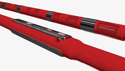
AFGLOBAL REPLACES RCD WITH NEXT-GENERATION MPD CONTROL DEVICE
The heart of managed pressure drilling (MPD) operations has undergone a significant advancement with the introduction of AFGlobal’s Active Control Device (ACD), Fig. 10. This next-generation technology replaces the rotating control device (RCD), to provide the prerequisite annular seal that enables MPD operations. The technology improves safety and performance in critical pressure control applications.
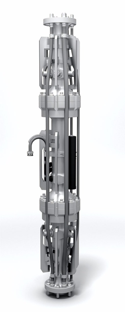
The ACD eliminates bearings and rotating components that are a regular source of maintenance and failure in standard RCDs. Instead, it provides an active pressure sealing system that hydraulically applies additional closing pressure, to maintain wellbore sealing integrity over time as the sealing sleeve is worn.
While the basic design for RCDs has evolved from early diversion devices used in air drilling, the ACD is designed specifically for MPD. It is API 16RCD-qualified to isolate and seal off the top of the riser, to divert mudflow during MPD operations.
The ACD is installed subsea in the marine drilling riser below the tension ring and slip joint. Configured as part of a riser gas handling system, the ACD enables MPD operations on floating drilling rigs. It can be adapted and installed to fit the riser system on any offshore drilling rig.
The ACD design replaces bearings and rotating components with a non-rotating sealing sleeve that uses direct hydraulic control and a co-molded element, featuring an enhanced urethane matrix, reinforced with a PTFE inner shell, to surround the drill pipe. As the sealing sleeve wears, pressure is applied actively, to force the element against the drill pipe to maintain a consistent seal. With RCDs, the passive rotating elastomer seal is degraded with use, causing a performance decline requiring regular replacement, along with the bearing assembly.
The active ACD seal has a stripping capacity 10 times greater than passive RCD elements. Pressure is applied continually to maintain consistent performance and greatly extend service life. Pressure applied to the active system is a positive wear indicator, improving seal maintenance scheduling and overall confidence in performance. To further improve seal life, pressure is varied easily to accommodate passage of tool joints. Unlike passive RCD systems, the ACD seal is lubricated with drilling mud to further enhance element life.
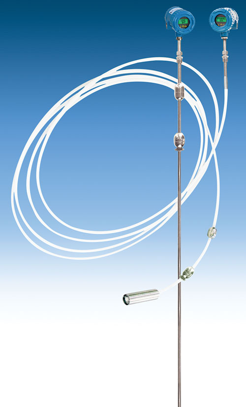
LEVEL MEASUREMENT SYSTEM HAS ENHANCED COMMUNICATIONS, MULTI-VARIABLE FUNCTIONALITY
AMETEK Drexelbrook has enhanced the communication capabilities of its Total Tank Level Measurement System to include Dual 4-20mA and Hart outputs, in addition to the standard Modbus protocol for measuring total level, interface level and temperature.
The versatile level measurement system is an accurate, cost-effective alternative to flexible stainless steel cable probes. It incorporates proven magnetostrictive sensing technology and features multi-variable functionality, Fig. 11. The system is accurate to 0.01% of measured span—less than 1 mm absolute—over the full measurement range.
The system’s intrinsically safe, explosion-proof design and all-welded construction make it an ideal choice for oil and gas storage tank and inventory control applications. Its five temperature sensors are distributed evenly over the active length of the polymer or stainless steel probe. The probe is available in a rigid 316 stainless steel version, as well as in flexible PVDF, in lengths up to 50 ft.
The system meets FM, FMc, ATEX and IECEX hazardous area approvals and requires minimal maintenance. A variety of floats and mounting accessories are available to fit virtually any application. The probes are offered with a choice of mounting configurations.
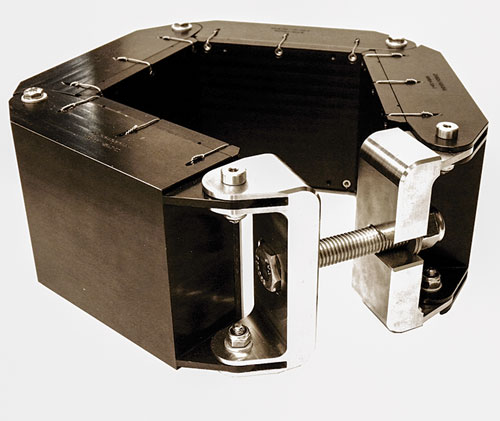
REAL-TIME DATA OFFER VIRTUAL VIEW DOWNHOLE
The XACT acoustic telemetry network offers a comprehensive virtual view of what is happening downhole and along the string, by transmitting measurements and other downhole data in real time. This can be done in almost any drilling or completions environment.
The platform can be used to monitor downhole dynamics during critical well construction operations, such as completion installation, liner running and cementing; pressure data visibility in under-balanced or managed pressure drilling; during well control, tripping, and other no-flow operations, as well as in high-loss environments.
The network of tools associated with on-site equipment and support is easy to use and integrates seamlessly into existing drilling and completion operations. The technology is independent of fluid type and isn’t restricted by circulation rate, high-resistivity formations or depth.
The nodes use the same threads as the drill pipe tool joints, and are spaced at predetermined locations within the drillstring to provide optimum signal strength and transmission range, depending on the angle of the hole. Once the acoustic signal reaches the surface, it is captured and wirelessly transmitted to an on-site computer by XACT’s patented C1D1-rated Electronic Acoustic Receiver (EAR), Fig. 12. The EAR has a dog collar-based design and is attached to the top drive, frac head, cement head, etc.
Repeater nodes along the string not only act as signal boosters, but also can take measurements independent of each other.
Weight, torque, pressure, temperature, bending and other measurements are displayed, and transmitted via WITS onto the rig and client networks. They also are ported to a highly secured server and web-based visualization service, allowing for remote viewing.
Data can be transmitted to the surface in real time, and/or held in memory until tripped out of the hole, and can be easily integrated with other data streams.
OIL-IN-WATER MONITOR USES OPTICAL RECOGNITION
Currently undergoing sea trials in the Norwegian North Sea sector, the Smart PFM 107 oil-in-water monitor (Fig. 13) measures particulates in the sample stream on a continuous basis. This is done by passing the process fluid through a proprietary photo optical measuring cell, developed by Rivertrace Technologies.
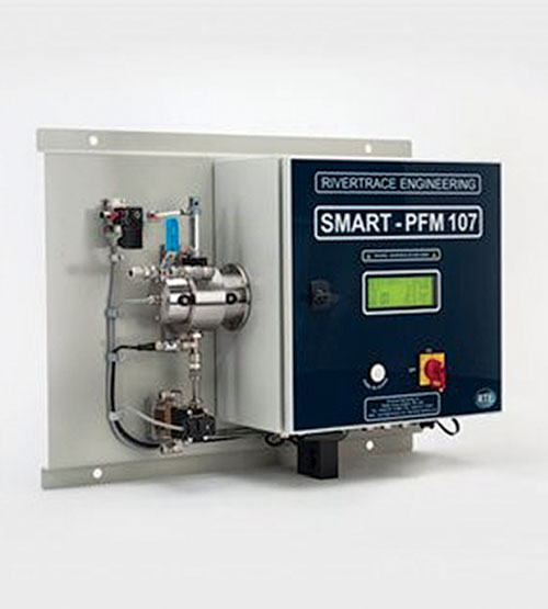
Using a combination of optical recognition algorithms and light intensity, it is possible to differentiate between oil particles, gas/air bubbles and solid particulates in the range of 0–500 microns. Unlike conventional monitors using light scatter or UV fluorescence, the Smart PFM 107 requires no re-calibration, if the oil varies from the standard calibration fluid, making it an ideal monitor for offshore platforms, drillships and FPSOs. Flow and particulate characteristics also can be visualized live, via remote access and optional dedicated software on any Windows PC.
Oil concentration, pressure, temperature, and alarm status are displayed on an LCD touch screen display. Oil concentrations, alarms and any faults are logged and stored within the system, to comply with the reporting requirements of IMO resolution MEPC 107(49), and can be accessed remotely or downloaded onto a PC via LAN or USB for further analysis. When connected to the Internet, it is possible for remote diagnostics to be performed by the manufacturer or an approved service center.
The Smart PFM 107 offers a choice of auto-cleaning methods to ensure that accuracy is maintained at all times. Dependent on the utilities available, one can choose from an air-driven solenoid, electronic actuator or high-power ultrasonic cleaning method. The cleaning is fully automatic and operates whenever the system senses contamination of the optical windows. The monitor is reportedly the only oil content monitor (OCM) on the market that comes with a standard choice of cleaning options, preventing fouling, the most common failure of any OCM.
FAST MAKEUP/LESS REPAIR YIELDS LOWER COSTS
NOV’s Grant Prideco business unit introduced the Delta drillpipe connection (Fig. 14), after extensive research into operator concerns. It aims to balance the need for high performance with the cost of running drillpipe effectively.
The Delta connection was engineered to be user-friendly. More threads engaged at stab and less rotation to engage shoulders results in reduced thread damage through the service life of the connection. The rugged thread design is well-suited to today’s drilling operations which, owing to their high level of automation, do not allow the use of a stabbing guide on the rig floor. The Delta connection makes up fast, with a spinning time that is about 50% lower than that of standard connections.
The Delta connection can be kept in service longer without worrying about the minor damage typically seen on drill pipe. Relaxed field inspection procedures and broader tolerances reduce the number of rejections, keeping the pipe in service longer and maintaining product integrity before repair is necessary.
When repairs are required, the connection provides 50% more opportunity for refacing, which is the least costly of all connection repairs. When chase-and-face is needed, the connection requires 30% less material than other comparative connections at the equivalent performance level. With a shorter tong-free area, the tool joints also offer more available tong space for such chase-and-face repairs.
Overall, the Delta connection yields high returns through increased performance and reduced total cost of ownership. ![]()
- Applying ultra-deep LWD resistivity technology successfully in a SAGD operation (May 2019)
- Adoption of wireless intelligent completions advances (May 2019)
- Majors double down as takeaway crunch eases (April 2019)
- What’s new in well logging and formation evaluation (April 2019)
- Qualification of a 20,000-psi subsea BOP: A collaborative approach (February 2019)
- ConocoPhillips’ Greg Leveille sees rapid trajectory of technical advancement continuing (February 2019)

