MPD and continuous circulation technology overcome deepwater challenges
Previous wells drilled by Murphy Oil Company offshore Sabah, East Malaysia, using conventional open wellbore drilling technology had experienced well control events and significant non-productive time. Conventional drilling problems encountered in the area’s shallow, multi-layer sandstone formations included kicks, stuck pipe, lost mud circulation, and differential sticking.
Implementing managed pressure drilling (MPD), as well as continuous circulation system (CCS) technology and processes, successfully mitigated these formation pressure-related challenges so that target depths could be safely and efficiently reached. A 13-well deepwater MPD program eliminated formation pressure problems seen on conventional drilling operations, and in the process performed the industry’s first deepwater managed pressure cementing (MPC) operation.
The innovative program used dynamic MPD formation pressure analysis techniques and LWD tools to reduce uncertainties in the extremely narrow formation pressure drilling windows.Operations were conducted from a deepwater moored spar platform in 4,400 ft (1,341 m) water depth. The 13-well campaign drilled 27 hole sections using MPD and CCS technology and methods.
Some sections were considered undrillable without MPD technology due to the narrow pore pressure/fracture gradient (PP/FG) window, high gas levels, and mud losses on some sections. A statically underbalanced, dynamically MPD overbalanced mud weight was used to widen the operational drilling BHP window and achieve the required BHP control.
SANDSTONE CHALLENGE
The field’s reservoirs are formed by relatively shallow, multi-layer sandstone formations at 8,202 to 10,006 ft (2500 to 3050 m) TVD. Production began in 2007, and was followed by a water injection program. Faulting has compartmentalized the reservoir, and there is a mix of depleted compartments that have been isolated from the water injection, and where virgin reservoir pressures may be encountered when drilling new wells. Dynamically overpressured sandstones also occur where water injection has supercharged the formation.
This formation pressure regime makes it difficult to predict the PP/FG window. The uncertainty has significant repercussions. For example, if a kick occurs when drilling through a weak, pressure-depleted sandstone layer into a lower overpressured zone, it may result in an underground blowout in the weak sandstone.
A narrow drilling pressure window also increases the chances of lost mud circulation during liner runs and cementing. It is difficult to achieve good zonal isolation above a depleted zone, as the heavier cement slurries can be lost to weaker formations. These challenges are compounded by well designs with high angle or horizontal hole sections that require considerable hole cleaning in the smaller production hole sections.
MPD/CCS SELECTION
This complex combination of depleted formations, narrow PP/FG windows, and high hole angle inclinations created a significant challenge when using conventional drilling practices. To improve safety and efficiency of operations, a drilling campaign was developed using MPD with a CCS. The initiative had several objectives, including reducing risk and NPT associated with lost mud circulation, kicks, stuck pipe, and wellbore collapse. MPD technology was implemented to improve management of downhole pressure and overbalance, hole cleaning in the high-angle wells, and event detection.
The MPD approach combined active, continuous control of hydrostatic and applied annulus pressure and flowrates while maintaining continuous drilling fluid circulation in a closed-loop circulating system. Techniques included dynamic MPD well control and formation evaluation, along with dynamic managed pressure cementing (MPC). MPD annular pressure and flowrate control was combined with a continuous circulating system using drillstring subs.
MPD/CSS EQUIPMENT
Installing the MPD package on the deepwater moored spar platform required detailed planning. The equipment occupied significant deck area and loading capacity, and hot work activities were restricted due to ongoing production from live wells. Surface MPD equipment was consolidated on the same deck to minimize interconnecting pipe work. Pipe work size was maximized to reduce the frictional flow pressure drop across MPD surface lines.
Continuous circulation system. The addition of CCS enabled maintenance of constant bottomhole pressure (CBHP) across the open hole section and provided continuous hole cleaning/cuttings transport during drill pipe connections. It also stabilized BHP and bottomhole temperature (BHT) conditions.
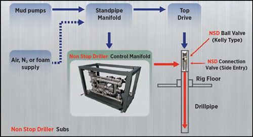
The CCS used rig pumps to provide continuous circulation down the drillstring while making or breaking drill pipe connections, Fig. 1. The system consists of a ball valve and a custom-designed high-pressure side entry valve housed in CCS drill pipe subs. Circulation is maintained throughout the connection by circulating into the side entry valve via a manifold interfaced with the rig standpipe manifold, a hose, and quick connector. A ball valve in the CCS sub is closed to bleed off pressure above it, allowing the drill pipe connection to be broken and a new stand made up while full circulation continues via the side entry valve.
MPD manifold. The MPD system’s pressure control and metering manifold (PCM) achieves accurate BHP control of +/– 30 psi and minimum liquid return flowrates of 1,700 gpm with an ASBP window of 15 to 1,350 psi.
The manifold uses a pressure relief system upstream of the PCVs and the Coriolis mass flow meters to protect the formation, casing, subsea and surface equipment from overpressure conditions. Four- and 8-in. Coriolis flow meters are used to measure drilling fluid return flowrates, along with fluid temperature and density. All remote-actuated valves are operated via the MPD SCADA system control panels, where positions are monitored and displayed.
Mud gas separator. Drilling mud returns and any entrained gas from the manifold enters the mud gas separator (MGS), where gas is separated out and the gas flowrate is metered using a laser particulate meter. The MGS is fitted with a centrifugal mud pump that can be used when drilling returns fall below 300 gpm to prevent drilled solids from settling in the MGS cone or return flow line.
KICK/LOSS DETECTION
The MPD drilling program used a standard MPD kick and loss event detection system. MFI derived data from stroke counters and MFO data derived from Coriolis flow meters are processed through an applied moving average SCADA data filter.
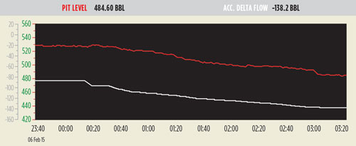
Proportional changes between the two flow readings are detected by the accumulative delta flow trend. The accumulative delta flow trend is the difference between MFI and MFO over time; instantaneous flow difference is the difference between MFI and MFO at a given time. A kick alarm is triggered when a positive change in the slope of the accumulative delta flow curve occurs with a formation fluid influx rate that exceeds defined section tolerance limits, Fig. 2.
Dynamic MPD well control response. The response to an influx is an increase in MPD ASBP to a predetermined pressure sufficient to reduce the influx volume. ASBP is increased until MFO equals MFI. The total kick volume taken is determined from the system once this flow equalization is achieved.
UPFRONT MPD ENGINEERING
An initial MPD feasibility and concept study was used to plan drilling in the narrow PP/FG margin formations. One of the key results was using a lower-than-standard mud weight to widen the operational drilling window while remaining dynamically overbalanced during MPD operations.
The study examined how to compensate for ECD loss when not circulating or during drill pipe connections using MPD ASBP. In these circumstances, conventional MPD systems with a backpressure pump are significantly limited in accurately maintaining BHP; with mud pumps off, only a single pressure point at a specific depth in the open hole section can be controlled by varying ASBP. This pressure control point is normally established at TD to prevent influx.
As a result, pressure at the weak zone is greater than when circulating and can exceed the fracture gradient, causing losses higher up in the open hole section. Alternatively, to prevent fracturing, this pressure control point can be at the weak zone. But this results in BHP at the bit being less than the circulating BHP EMW. If this pressure falls below the pore pressure, it can cause a wellbore fluid influx [kick].
This limitation was mitigated using CCS to maintain constant BHP and ECD along the entire open hole section during drill string connections. Using CCS also eliminated pressure surges when starting and stopping circulation, further enhancing BHP control. The study concluded that combining the CSS with the deepwater MPD system would enable maintenance of a truly constant wellbore pressure profile while drilling and making connections.
FEED optimization. A detailed front-end engineering design (FEED) was executed, including MPD and CCS operational procedures, MPD well control procedures, bridging documentation, project drawings, and project steering documentation. After completion of a HAZID study and prior to the design being locked in, a detailed HAZOP study was conducted to comprehensively and systematically identify all the hazards and operability problems of the MPD project.
Hydraulics modeling. Hydraulics modeling was performed prior to drilling each well. The study considered drilling margins between pore pressure and fracture gradient, maximum allowable standpipe pressure, maximum allowable ASBP, targeted BHP, and hole cleaning requirements.
Mud weight, pump rate, and ASBP for each MPD hole section was determined by steady state simulations performed at the shoe and total depth. These measurements were used to ensure BHP and ECD remained within the drilling window during MPD drilling and connections. Mud weights were statically underbalanced /dynamically MPD overbalanced, or slightly statically overbalanced based on the pressure window prognoses and level of uncertainty.
Steady state MPD simulations were also used to determine the ASBP for a number of MPD operations, including dynamic MPD FIT and LOT, mitigating influxes, and determining the effects of drillstring rotation and rate of penetration on ECD.
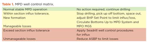
Well control simulations. An MPD well control matrix was prepared detailing well control actions to be taken by the MPD operator and driller once an influx was detected and confirmed, Table 1.
The criteria for selecting dynamic MPD or conventional well control is the section influx tolerance (SIT) determined by the amount of gas kick in barrels that can be circulated out of the well using the MPD system and riser without fracturing the formation or exceeding MPD surface equipment pressure rating limits. Conventional well control is used if the influx volume exceeds the SIT.
Simulations used a dynamic kick control hydraulics model to safely circulate influxes of various sizes out of the wellbore. Because the MPD system can accurately detect a formation fluid influx of 2 bbl or less, the influx volumes considered in the analysis were limited to 15 bbl.
A transient drilling simulator hydraulics model allowed modeling of extended back reaming, stripping, and well displacement operations. A MPD ASBP backpressure schedule compensated for the loss of circulating pressures as the drillstring was pulled out of hole from TD up to the 30° hole inclination angle in the 9 5/8-in. casing. The objective was to maintain constant BHP at a control point in the open hole and ensure that the well was taking the correct mud displacement during tripping operations.
MPD STRATEGY
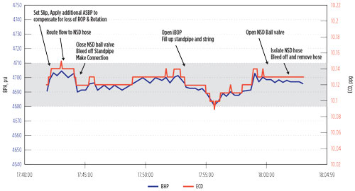
Stopping and starting the rig’s circulation system is a primary source of drilling NPT resulting in lost circulation, kicks, sloughing, stuck pipe, and differential sticking. A key drilling strategy was to use CCS to keep the pumps running at all times to provide a safe, simple, effective MPD solution. Figure 3 illustrates making a connection with the CCS system to maintain +/– 15 psi BHP control accuracy during drill pipe MPD connections. An additional 100 psi MPD ASBP was applied during the connection to compensate for the loss of drilling ROP and RPM.
CCS is the first step in MPD management of wellbore pressures and avoiding significant pressure variations during drill pipe connections. Using CCS with a MPD system allows a constant ECD profile to be maintained along the entire open hole section while drilling and making connections. Its use avoids the need to re-establish steady state circulating conditions required when using conventional drilling or standard, older type MPD techniques.
Once continuous circulation is established, MPD allows formation pressure and fracture pressure profiles to be determined. This supports active and continuous BHP control within the PP/FG window. MPD techniques were used to perform dynamic flow checks, dynamic FIT and LOT, squeezing lost circulation materials (LCM), kick and loss detection, dynamic well control, CBHP methods, and MPC.
Execution of the well control matrix is achieved using dynamic MPD well control to increase the BHP until MFI equals MFO to stop the influx and circulate it out of the wellbore without shutting in the well using the rig BOPs.
The pore pressure trend illustrates the degree of formation depletion or overpressure, which determines whether the current MPD drilling mud weight is statically overbalanced or underbalanced with respect to the highest pore pressure encountered.
The lower pressure boundary for the drilling window is constrained by pore pressure or the minimum pressure required for wellbore stability, whichever is higher (typically the latter in this case). The higher boundary is established by performing dynamic MPD FIT / LOTs or dynamic MPD flow checks when mud losses are encountered.
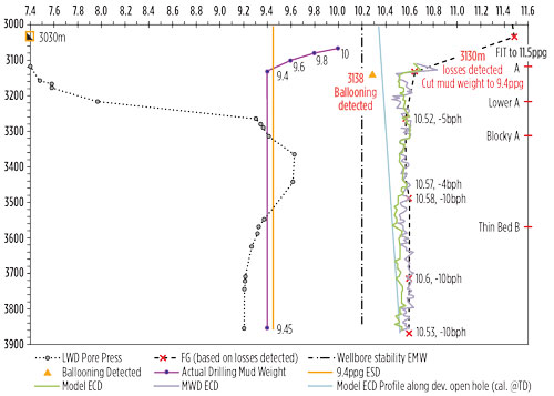
For example, drilling operations in one of the wells performed a MPD FIT to 11.5 ppg EMW, indicating the presence of a usable mud weight window, Fig 4. Due to high ECD with 10-ppg mud, weight was reduced 9.6 ppg. Drilling continued to the top of the A formation, where the LWD pore pressure tool was deployed to determine a formation pore pressure of 7.23 ppg.
The mud weight was reduced to 9.4 ppg when mud losses were detected by the MPD system. Increased return flow was detected within 8 m of drilling, when ECD fell below 10.3 ppg when rig pumps were cycled for an MWD directional survey. After that point, ECD was maintained above 10.3 ppg EMW to prevent flow back from the formation. The formation pore pressure ramped up to 9.62 ppg as drilling continued into the formation. Minor mud losses were observed in the B formation if ECD exceeded 10.6 ppg EMW.
Managed pressure cementing. The 8.5-in. hole section on the same well was drilled using MPD with a statically underbalanced and dynamically MPD overbalanced EMW. Mud losses at the top of the A formation required a dynamic MPD flow check that indicated a 10.52 ppg fracture gradient. Formation flowback was detected when ECD dropped below 10.3 ppg during an MWD survey a few meters from the loss zone. The resulting drilling window was 0.2 ppg EMW or 88 psi between flow-back into the well bore and losing mud into the A formation. In addition, seepage losses were observed in the B formation when ECD exceeded 10.6 ppg EMW.
The narrow window required precise BHP pressure control in order to maintain constant bottom hole pressure in the depleted zone. The information gathered using MPD techniques was critical to prevent influxes and losses during cementing operations.
There were two key cementing objectives for this smart injector well: provide good zonal isolation of the depleted A formation and critical injection zones; and eliminate the cost of running an additional liner extension tie-back in the event cement could not be placed above the depleted A formation and top of liner hanger.
MPC discussions began during drilling operations when it became apparent that conventional cementing techniques would fail to meet the objectives. The result was the first deepwater MPC operation successfully executed globally. It presented significant challenges due to the narrow pressure margin, as this was a deepwater well with an 88 psi drilling window, with high fluid mobility.
A fast-track MPC initiative identified the key tasks required to cement the well using the MPD system. The first task was to simulate the planned cement job and develop an ASBP backpressure and pumping schedule. A MPD cementing procedure was written based on the cement program and recommendations from the MPD hydraulics simulation. A contingency plan was created and the MPD system was swiftly customized for safe, efficient MPC operations.
The procedure involved running the 7-in. liner very carefully to manage surge pressure, losses, and ballooning. Once the liner was set, the well was displaced to underbalanced fluid using the predefined pumping and MPD ASBP backpressure schedule to maintain constant BHP.
The liner was cemented while managing a pressure schedule with multiple fluid gradients in the well. Concurrently, the ASBP was reduced to transition the well from a dynamically MPD-underbalanced state, to a statically overbalanced state with cement in place. The liner packer was set and tested, and excess cement was circulated out of the hole.
MPD/CSS ADVANTAGE
MPD with CCS was used to drill a total of approximately 42,979 ft (13100 m). Up to 60 CCS subs were made up in the drillstring to perform back reaming in the deviated and horizontal hole sections. A total 939 CCS connections were made during the project campaign with a 99.5% success rate. The average drillstring connection time using CCS equipment was 10 min. and the total slip-to-slip average connection time was 18 min.
The operations achieved greater understanding of real-time wellbore and formation pressure, and applied that to avoid pressure-related drilling problems that previously compromised safety and efficiency, and in some cases precluded any drilling at all. ![]()


- OTC recognizes 2026 Spotlight on New Technology® Award winners (April)
- SBM executive sees strong FPSO market on back of deepwater trend (April)
- IPAA’s annual meeting to re-visit site of association’s founding (April)
- First Oil: Trump administration makes a common sense move regarding offshore regulation (April)
- Engineering for the deep: Human support and rescue systems (November 2025)
- First Oil: Honoring the very best of some really outstanding technology (October 2025)
- Subsea technology- Corrosion monitoring: From failure to success (February 2024)
- Applying ultra-deep LWD resistivity technology successfully in a SAGD operation (May 2019)
- Adoption of wireless intelligent completions advances (May 2019)
- Majors double down as takeaway crunch eases (April 2019)
- What’s new in well logging and formation evaluation (April 2019)
- Qualification of a 20,000-psi subsea BOP: A collaborative approach (February 2019)

