JAMES F. LEA, PL Tech LLC; and HERALD W. WINKLER, Texas Tech University
Continuing last month’s listings of new innovations in artificial lift, this second-half report will cover 19 developments in the categories of electrical submersible pumps (ESPs)/downhole pumps; chemical and injection pumps; and measurement and surveillance devices and systems, including several items that arrived after Part 1 went to print.
In the category of ESPs and downhole pumps, there are eight items, ranging from a new, high-temperature ESP system to a hydraulic deliquification system. As regards chemical and injection pumps, offerings include a solar-powered chemical injection system and a linear drive injection system. Finally, in the broad category of measurement and surveillance devices and systems, new developments include such items as wellhead management; tank level measurement; and a lift management platform featuring monitoring, diagnostics and optimization. Continuing the rod/beam pumping category from last month, an innovative cage insert with better flow characteristics is described.
ESPs/DOWNHOLE PUMPS
About 15% to 20% of wells worldwide are pumped with some form of artificial lift employing ESPs. ESP systems have been a fast-growing form of artificial lift pumping technology. They are often ideal for high-volume and depth applications. This section describes eight new items.
New-generation, variable-speed drive improves ESP performance, wellsite safety. Baker Hughes has introduced the Electrospeed Advantage variable-speed drive (VSD) for ESP systems, Fig. 1. Advanced features optimize production, improve pump system reliability, and enhance safety at the wellsite.
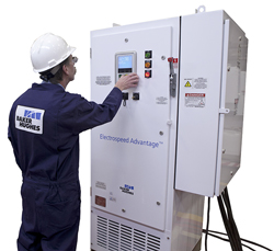 |
| Fig. 1. The Electrospeed Advantage VSD introduces a completely new control platform. |
|
This VSD introduces a completely new control platform while leveraging field-hardened electronics. For example, expandable software solutions help mitigate gas locking and fluid pump-off by automatically varying pump speed, based on torque variations. Software solutions also adjust the system’s V/Hz ratio to optimize power transfer to the ESP motor. In addition, they keep the ESP system running through brief power sags and outages. Software can be upgraded through a USB port in the door without exposing the operator to dangerous voltages. Many more software solutions are available to address other aspects of oil and gas production, such as drawdown management.
If system maintenance requires opening the unit, shielding within the new drive reduces the risk of electrical shock. A technician can take measurements, however, through strategically located test ports in the clear shields to facilitate electrical measurements while minimizing risk of electrical contact.
The VSD also is seamlessly compatible with comms-on (communication via ESP power cable) downhole sensors that measure temperature, pressure, flowrate and pump performance. These sensors are monitored by the Baker Hughes Vision web-based monitoring service. This service monitors thousands of wells worldwide, optimizing production and well system performance through advanced exception reporting and innovative mathematical modeling. ESP experts at the company supervise all well monitoring from strategic locations around the world. The VSD is NEMA 4-certified and can operate in ambient temperatures from -40°F to 131°F.
High-temperature ESP system extends run life and reliability. Operators in Canada’s heavy oil fields and in the Middle East are hoping to reduce workover costs through the use of the REDA HotlineSA3 high-temperature ESP system. The pre-assembled design (Fig. 2) inherent in this system positively impacts reliability and speeds installation. This new-generation, high-temperature system incorporates an integrated design aimed at effectively extending the ESP operating envelope and run life. This ESP, designed to produce from wells with bottomhole temperatures up to 250°C, can be installed during the early stages of development, giving the operator control, when pressure and temperature are highest.
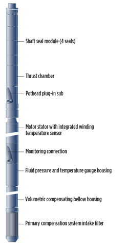 |
| Fig. 2. The Hotline SA3 high-temperature ESP system is designed to extend run life and reliability, thereby reducing workover costs. |
|
Integrated surveillance and control through reliable fluid pressure, temperature and internal motor temperature measurements help to reduce sub-cool and steam/oil ratio. The system motor is comprised of high-temperature materials rated to 300°C and is factory-filled with specially treated, ultra-dehydrated di-electric oil.
The system includes the multifunction motor unit, thermally compensated pumps, downhole monitoring gauges for pressure and temperature, power cables, and a surface controller. A plug–in, high-temperature motor lead extension has a dual, elastomeric seal. The motor electrical port connection has a positive pressure system that prevents fluids from escaping or entering during connection.
Hydraulic deliquification continues to prove itself. Cormorant Engineering designs, develops and markets hydraulic deliquification systems, Fig. 3. The systems are optimally designed for specific wells (addressing high dogleg severities, high solids, coalbed methane, etc.) and include options for horizontal and vertical applications. The company has conducted pre-deployment testing (endurance testing of seals, other downhole and surface components) and well scenario modeling via proprietary software.
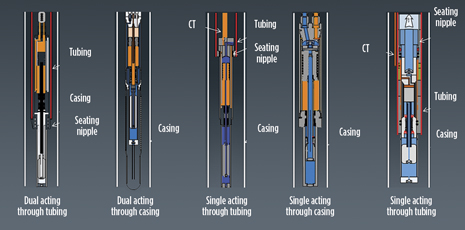 |
| Fig. 3. Currently designed hydraulic dewatering pump systems available at Cormorant Engineering. |
|
Current pump designs can be divided into two types of systems:
-
Through Tubing (TT). The hydraulic pump is run on coiled tubing (CT) through the production tubing and seated in a seating nipple at the bottom of the tubing. The CT is full of hydraulic fluid. The water is pumped up the CT/tubing annulus. Gas flows up the tubing/casing annulus.
-
Through Casing (TC). The hydraulic pump is run on a FLATpak, which is composed of two or three CT strings. Either one or two CT strings are full of hydraulic fluid. Water is pumped up the remaining CT string(s). Other deployment methods include concentric coil (CC) or production tubing (PT).
The hydraulic power unit (HPU) at the surface applies hydraulic pressure to the downhole pump, pushing the power piston up, Fig. 4. The HPU then releases the hydraulic pressure and allows the hydraulic fluid to drain back to the tank. The difference in fluid density between the pumped water and the hydraulic fluid provides the restoring force that pushes the power piston downward. This type of pump actuation is referred to as a Single Acting System (SAS). A Dual Acting System (DAS) uses hydraulic pressure supplied from the HPU to move the power piston up and down.
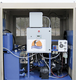 |
| Fig. 4. Hydraulic power unit with remote monitoring via the web. |
|
Current hydraulic pumps are designed to operate at 15,000 ft, TVD. The range of liquid production is from 5 to 100 blpd. A new focus of the technology is to address applications beyond 10,000 ft, TVD, and high dogleg severities (> 15°/100 ft).
As of March 2012, seven of these systems have been manufactured and installed. The field applications span a variety of downhole environments. One such system, DAS-deployed TC, is in the Fayetteville shale (high solids environment), horizontal at 3,000 ft, MD. An SAS-deployed TT is in the Fruitland Coal (CBM application in Farmington, New Mexico), vertical at 2,000 ft, TVD. Typical water production from these examples ranges from 5 to 30 bpd.
ESP gauge is ground fault-immune. Zenith Oilfield Technology has introduced an ESP gauge that is immune to ground faults, a persistent problem with artificial lift that affects more than 15% of downhole monitoring systems.
The Ground Fault Immune gauge (Fig. 5) runs a new power and communication system, so that insulation breakdown caused by ground faults will not short the system. The monitor will continue to run, as long as the ESP cable is operational. For the first time, this gauge offers a monitoring solution that cannot be disturbed by these types of faults.
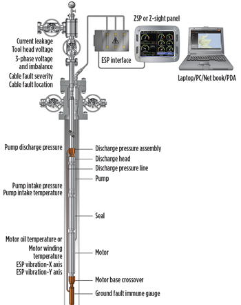 |
| Fig. 5. The Ground Fault Immune gauge runs a power and communication system, so that insulation breakdown caused by ground faults will not short the ESP system. |
|
Usually, a ground fault will cause downhole monitoring systems to fail and leave operators running blindly. They have to run motors at lower pumping rates to keep motor temperatures in safe operating areas, and also with a larger head of fluid to avoid pump-off. This can result in up to 25% reduction in fluid output, compared to a pump optimized with a live downhole gauge, resulting in a significant loss of production.
The Zenith technology has recently been proven in tests in the Middle East, with numerous operators keen to deploy the new system with installations that were planned from April forward. The system can operate at 125°C and at pressures of up to 5,000 psi. Logging data at 0.5 seconds per reading, the logger software and diagnostic panel allow for gauge sensor readings on a real-time plot, which can be scaled and adjusted.
Downhole monitoring specialist Zenith Oilfield Technology is headquartered in Aberdeenshire, UK and became part of Lufkin Industries Holdings UK Limited in February.
GrindStone pump handles abrasive particles. Well environments that contain highly-abrasive and heavy native particles, including iron sulfide, coalbed methane and sand, are known to have negative effects on artificial lift production. These heavy and soft particles can be produced through ESP systems, but they often lack the fluid velocity to reach the surface. This can cause pump stage wear or clogging. This premature wear reduces production and prematurely decreases ESP run times.
The GE Oil & Gas GrindStone particle-reducing pump (Fig. 6) grinds abrasive particles, to enable easy passage through the pump in harsh environments. The bolt-on compression pump sits below the main pump and features clog-resistant, stainless steel stages designed to grind and cut particles before they pass through the pump. This particle-reducing design (Fig. 7), paired with high-strength shafting and tungsten carbide bushings in the head and base, enables the pump to reduce the effects of deposition, decrease fluid velocity costs and, according to lab simulations, extend ESP pump life by up to 50%.
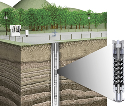 |
| Fig. 6. The GrindStone pump from GE reduced premature ESP wear by grinding abrasive particles, to enable easier passage through the pump in harsh environments. |
|
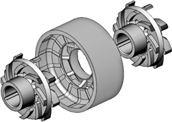 |
| Fig. 7. Stages of the GrindStone pump. |
|
Protecting ESP system integrity protected by MVD/VSD. Variable speed drive (VSD) systems are used to protect and control ESPs, as well as surface pumping systems. Low-voltage and medium-voltage VSDs are designed to extend ESP life while cutting operational costs. The Schlumberger SpeedStar MVD/VSD NEMA 3R option (Fig. 8) is a medium-voltage drive (MVD) designed for outdoor installations. For high-horsepower, high-value applications in a single package, this MVD is designed to provide reliable, efficient control.
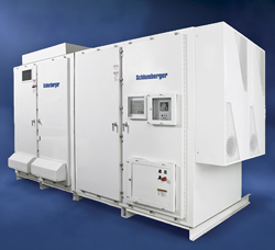 |
| Fig. 8. The Speedstar medium-voltage VSD extends ESP life while cutting operational costs, particularly offshore. |
|
The MVD does not require installation in a climate-controlled environment, which the company claims is an industry first. Additionally, the system is engineered to fit remote applications, where building infrastructure is unavailable or nonexistent. The MVD includes an optional marine version that is suitable for outdoor use in nonhazardous and harsh environments, typical with platforms or offshore applications. An integral, application-insensitive sine-wave output filter eliminates resonance, regardless of variations in cable length and motor type. This produces nearly sinusoidal output voltage and current, that ensure speed control without a speed-sensing device.
The MVD also comes equipped with a high level of safety that includes a visible disconnect switch interlocked with Kirk keys, to protect personnel and assets.
ESPCP solution provides high production from small-diameter wells. Baker Hughes recently introduced a new electrical submersible progressing cavity pumping (ESPCP) system (Fig. 9) that can be deployed through 2⅞-in. or 3½-in. tubing and is capable of lifting 330 bpd.
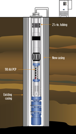 |
| Fig. 9. Tested on Alaska’s North Slope, this new ESPCP system can be inserted and retrieved through tubing without pulling pipe. |
|
The system was installed via wireline in two wells on Alaska’s North Slope in late 2011 and early 2012. The wells had experienced casing leaks and were repaired with new casing, whose smaller diameter prevented re-use of the existing, tubing-conveyed ESPCP systems. With a 2¼-in. OD, the new ESPCP system enabled the operator to resume production at the desired volume. In addition, the system can be inserted and retrieved through tubing without pulling pipe.
To meet this application’s demands, the firm developed a 110AA multi-lobe PCP system with a 2¼-in. OD stator housing, capable of producing 330 bpd at 300 rpm. The patented downhole system consists of a progressing cavity pump, gauge, motor, gear reduction unit and seal.
By using a multi-lobe pump design (2:3), the system can handle higher volumes than single-lobe PCPs (1:2) and is more efficient than other artificial lift options, such as jet pump systems. The new system met the operator’s objectives for improved production and operating efficiency with a design that minimizes intervention costs.
Optimizing progressing cavity pumps. The acceptance of progressing cavity pumps (PCPs) in the industry has grown worldwide. PCP operators’ primary goal is to extend pump run life while producing all available fluid. The challenge is to produce the well without starving the pump and causing stator damage.
Kudu has made several advancements in fluid flow measurement by utilizing proven algorithms that optimize production. It combines wedge meter flow technology and microprocessor control of both electric motors, using variable-frequency drives, and hydraulic motors using proportional control valves. The PCP Well Manager is a controller that produces all available fluid from the wellbore without damaging the pump. This automated technology uses a web-based SCADA system that monitors several data trends and detects hidden production points.
Kudu and Lufkin Automation have joined forces to offer an innovative system for maximizing performance in PCP wells. This smart well technology seeks and detects hidden production points to ensure that the well is always pumping at optimum levels. The PCP Well Manager optimizes production by measuring flowrates, monitoring torque and adjusting pump speed. The data is logged in real time, and enables the operator to view and implement changes remotely, anytime and anywhere.
The system has two main objectives—one is to reduce premature pump failure, and the other is to automatically optimize the well. Controlling PCPs reduces premature pump failures due to pump-off, which is a lack of fluid in the pump that leads to stator damage. This lack of lubrication creates a temperature rise and ultimately burns the elastomer in the pump. The stator’s rubber surface becomes hard, brittle and cracked. In severe circumstances, stator contour is completely torn up, producing rubber at surface. Plugged pump intake, poor inflow or production rates exceeding inflow are typically to blame.
There are several problems associated with maintaining a safe fluid level while using manual fluid level equipment. Fluid levels indicate how much fluid is over the pump at the time the level is taken. Fluid levels are constantly misinterpreted, due to surface rod noise and foam. Downhole anomalies, such as high liner tops, bad doglegs or other “non-standard” configurations, will result in false fluid level data. It is extremely time-consuming to shoot fluid levels, adjust speed and allow the well to stabilize and shoot the level again. This manual process does not react quickly enough to changes in inflow.
The PCP system eliminates fluid level monitoring problems and actually increases overall production by keeping the fluid at or near the pump. It sustains optimum fluid inflow by maintaining the lowest bottomhole pressure possible. The system’s ability to pump over capacity empowers it to recover quickly from downtime.
The PCP control algorithm is the brains of the system. It optimizes well production without causing pump-off. This patented control algorithm varies pump speed in steps while measuring fluid production. As long as sufficient fluid is available at the pump intake to completely fill the pump cavities, a linear relationship occurs between fluid production and pump speed. This hunting algorithm is always searching for the most production. The system continues to increase pump speed in user-defined steps and measures the production rate, after the settling time, of each step to establish an optimal speed/rate relationship.
Among field study results and historical data, a 15-well pilot project started in January 2007 included the host SCADA system and the PCP VFD combo unit, complete with wedge flow meters. The result was increased average oil production, from 120 m3/day, to 145 m3/day. An unexpected benefit was increased average gas production, from 19 to 23 dec/day. This showed an estimated payout in 120 days, Figs. 10 and 11.
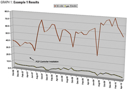 |
| Fig. 10. Oil production increased from 120 m3/day, to 145 m3/day. |
|
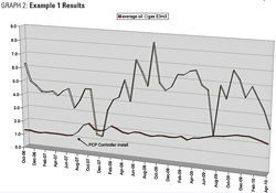 |
| Fig. 11. There was an unexpected benefit of increased average gas production, rising from 19 to 23 dec/day. |
|
Second, a single well pilot started in December 2009 was continually failing. Before optimizing the well, the focus was on producing the sand that was preventing the well from running. By bringing the well on slowly, and limiting the maximum speed over four stages, the sand was cleaned up to a manageable level. Revenue for this well increased from $0/day to $7,798/day, with an oil gain of 19.4 m3/day, Table 1.
| Table 1. Revenue, pilot well installation. (Click to enlarge) |
|

|
Last, a single well pilot started in July 2008 had extreme production difficulties. For the first six months prior to installation of the PCP controller, this Bakken well had four pump changes, due to sand and inflow issues. The well produced 2,711 m3 with an operational cost of $198,000. On July 1, 2008, Kudu installed a 60K1200 pump and added the hydraulic PCP controller with a wedge flow meter. For the next six months, the well produced 19,779 m3 with no workovers. The pump ran for 14 months before it needed to be changed out, due to wear and tear from abrasion.
CHEMICAL/INJECTION PUMPS
Solar-powered and linear drive systems comprise this year’s offerings.
Solar-powered chemical injection system. To address limitations in existing wellsite chemical pump technology, Ferguson Beauregard designed the iChem Solar Powered Chemical Injection System. iChem was created through a joint venture between Ferguson Beauregard and fellow Dover Corporation subsidiary, Neptune Chemical Pump Company. Midstream operators employing iChem will benefit from real-time knowledge of pipeline pressure at injection points, chemical tank levels, and automated temperature-based pump control.
The iChem system offers leak-free, easy-to-select, exceptionally accurate injection volumes (up to 45 gal/day) for well pressures of up to 1,200 psi. The heart of the iChem system is a hydraulically balanced diaphragm metering pump (Fig. 12), based on a Neptune design that features a brushless motor paired with a digital controller. The diaphragm metering pump’s seal-less design eliminates leaks while greatly reducing maintenance calls and downtime. The absence of O-rings on the pump’s wet end permits compatibility with a wide range of chemicals.
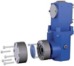 |
| Fig. 12. At the heart of the solar-powered chemical injection system is a hydraulically balanced diaphragm metering pump. |
|
A user-friendly digital controller with numeric keypad and LCD display makes for simple, precise calibration. Prescribed chemical volumes can be programmed without overdosing to compensate for pump inaccuracies, often resulting in significant chemical cost savings. Adding a tank level measurement option allows real-time knowledge of storage tank chemical levels, thus promoting efficient management of trips to wellsites to refill chemical tanks. During winter months, the automated temperature control option enables chemical injection when temperature (air or flowstream) reaches a user-selectable value, injecting freeze-preventing chemicals only when needed.
The solar-powered system (Fig. 13) has been engineered to run independently of the well with an extremely low energy draw. At the same time, it minimizes environmental impact by eliminating gas emissions and chemical leaks, and reducing chemical consumption and trips to the well.
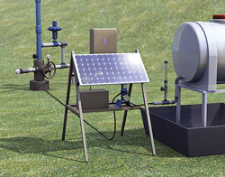 |
| Fig. 13. The solar-powered system has been engineered to run independently of the well with an extremely low energy draw. |
|
Linear drive chemical injection system. Linear drive technology has been used in the machine tool industry for many years. When it comes to moving a large load with high precision and accuracy, while using a relatively small horsepower drive motor, linear drive has long been the drive of choice. D&D DesignTech, Inc., has been able to create a chemical injection system that possesses many of the attributes generally found in linear drive systems.
A few of these attributes include high torque-to-power ratio, repeatability, accuracy and reliability. Using a small motor (Fig. 14), this system can achieve injection rates up to 9 gal/day at 5,000 psi and 18 gal/day at 1,500 psi, with other options available. Accuracy and repeatability are achieved and maintained through drive and positioning feedback. Positioning feedback allows the pump system to be minimally affected by changing pressures at the discharge of the pump. Reliability is achieved with the use of an all-solid state control system and the incorporation of a high-torque brushless DC motor, driving a precision linear drive mechanism.
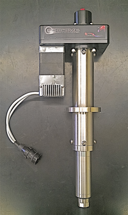 |
| Fig. 14. The linear drive system can move a large load with high precision and accuracy, while using a relatively small horsepower drive motor. |
|
The use of a solid state, programmable controller (Fig. 15) allows different types of sensors to be interfaced for system verification, including tank level, fluid output, battery voltage, pump alarms, and even remote standby.
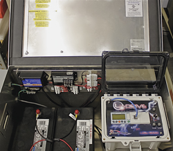 |
| Fig. 15. The linear drive system’s programmable controller allows different types of sensors to be interfaced, and it can be monitored remotely. |
|
The controller also can be monitored remotely via satellite transmitter or SCADA. Along with monitoring the system, injection parameters can be modified from a remote location. When monitored via satellite, data are downloaded up to four times per day and archived to be used as an audit trial for the system. These data can then be downloaded to a legacy SCADA system, allowing the user to have access to both types of data. Power for this system can be either 120 VAC or 24 VDC, using batteries and solar charging.
Programming the system is as easy as entering a desired injection rate and a stroke size, using the LCD display and pushbuttons on the controller’s front panel. Proportion-to-flow pumping is also an option that can be used by tying the controller to an analog output from an existing flow device. This system has one patent that has been applied for and is in the final phase of testing for a Class 1, Division 2 hazardous location certification.
MEASUREMENT/SURVEILLANCE
One of the larger sections in this year’s Artificial Lift compilation is the category of measurement and surveillance devices and systems. Five items are included.
New system ensures accurate, reliable production tank level measurement. Ferguson Beauregard’s new iLevel Tank Level Measurement System is based on proven, magnetostrictive probe technology developed by fellow Dover Corporation company, OPW Fueling Components. The stainless steel probe (Fig. 16) is resistant to corrosion and features a one-piece, welded head design that eliminates all potential leak points, resulting in long-life reliability and durability.
 |
| Fig. 16. The iLevel Tank Level Measurement System utilizes magnetostrictive probe technology. |
|
The system’s liquid level sensor is certified for Class I Div. I tank environments, when used with the company’s solar-powered iLevel multi-tank controller mounted in the Class I Div II area. The iLevel design enables measurement of two liquid levels in each tank, such as oil and water. For large tank batteries, the system can be expanded to economically monitor up to 24 tanks through a single easy-to-configure controller interface.
Real-time tank level knowledge enables the dispatching of water or oil haulers to well sites as needed. Additionally, the system is powered by a solar rechargeable battery located on the ground level controller. This design eliminates the need to climb to the top of the storage tanks to replace probe batteries (Fig. 17).
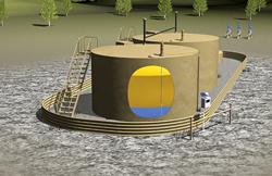 |
| Fig. 17. A solar rechargeable battery located on the ground level controller enhances operator safety by eliminating the need to climb to the top of the storage tanks to replace probe batteries. |
|
The iLevel communicates via a serial connection, wirelessly through a 900-MHz or 2.4-GHz radio, or serially via a cell modem. The system supports the MODBUS protocol, resulting in an interface that does not require a custom communications driver. The system is compatible with most RTUs and connects directly to most SCADA host systems, allowing real-time, accurate knowledge of tank levels.
Software platform delivers lift management monitoring, diagnostics and optimization. Reservoir conditions change over time, and meeting production targets is a continuous challenge. The Avocet production operations software platform from Schlumberger delivers a broad range of solutions to see a clear, complete, up-to-date picture of operations, and understand the root causes of production shortfalls to enable action to maximize output through optimization. The platform now includes an option for online artificial lift management capabilities for both ESP pumps and gas lift operations.
The lift management solution within the platform incorporates map-based navigation and alarm notifications for monitoring purposes, as well as an ability to track downhole ESP configuration and related run life operational activity. The software can determine operating conditions and estimate flowrates on the surface. Patented algorithms within the software platform are used to optimize production rates, based on available power to run ESPs, or with available gas for gas-lifted wells.
Surveillance of incoming data and the retrieved results can be run continuously. Resulting set points can be published back to the operator, displayed in any remote engineering desktop or displayed using a Web client that displays alarms and key performance indicators. Reports can be generated automatically or on demand. Longer-loop cycles are also considered as part of an integrated service, with analysis of results and production history for optimized strategic decision-making.
The identification of production optimization opportunities using an integrated management system can increase potential per well by an average of 20%.
Intelligent control system displays, analyzes well data and centralizes logic. The days of going downhole blindly are quickly decreasing, as operators see the numerous benefits that can be realized using on-site and remote monitoring and control technology. GE Oil & Gas conducted extensive field trials and recently launched a new “smart” remote monitoring and diagnostic technology, the Apollo Intelligent Control System, Fig. 18. This device displays and analyzes critical well data and provides advanced machine control by centralizing logic previously split between human machine interfaces (HMI), drives, downhole sensors and other site-control devices.
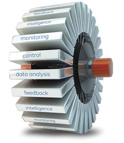 |
| Fig. 18. The Apollo Intelligent control system displays and analyzes well data, and centralizes logic. |
|
Offering a standardized hardware and software control interface, the Apollo system can be applied to products across the artificial lift industry. Apollo expands input/output (I/O) capabilities, customizes advanced control functions, and improves functionality when added to a Vector VII drive, new or existing switchboard, full-voltage motor starter, or solid-state, reduced-voltage motor starter (Soft Start). When used in conjunction with ESP downhole pumps or surface pumping systems (SPS), improved protection, added control and expanded monitoring capability can also be achieved.
Products can be retrofitted with Apollo, and are supported by a customizable, application-specific, menu-style HMI configuration system that includes quick-start templates. For remote monitoring needs, the system also includes an advanced SCADA interface with a configurable modbus map and SCADA diagnostics.
This monitoring tool reduces mechanical issues by initiating warning alerts or an automatic shutdown, if the performance curve reaches a fault band. Thrust limits derived from real-time pump curve data also help increase the pump’s service life. The improved functionality of the system was tested in field applications and is approved for operating temperatures between -20°C and 70°C.
The system provides a new level of easy-to-use remote monitoring and diagnostic technology. This system’s ability to reduce equipment down times, increase product reliability, provide real-time pump performance data, and provide mechanical and electrical equipment protection, gives it an advantage. Its continuity across diverse operating platforms also enables users to reduce training costs and increase profitability.
Wellhead controller optimizes several functions. The AutoCycle iC wellhead controller from Ferguson Beauregard addresses such bottom-line-improving items as cost-effective wellhead optimization, real-time surveillance and control. The controller is a seamless wellhead management solution that enables users to remotely monitor tank levels, wellhead pressures, flowrates and control plunger cycles.
The controller offers the familiar control panel appearance (Fig. 19) and proven menu-driven program design for on-site adjustments. In addition to the company’s plunger velocity self-adjusting control algorithm, the controller also features a variety of additional control methods, including close-on flowrate and open-on load factor.
.jpg) |
| Fig. 19. The AutoCycle iC wellhead controller features a familiar control panel appearance and menu-driven program for on-site adjustments. |
|
This device seamlessly integrates with most host SCADA systems, including CygNet and Wonderware. The controller features two-way text messaging and connectivity with any SMS text-enabled cell phone. This allows the operator to remotely check current well status, change operating parameters, and receive scheduled messages and real-time notification of alarm events.
Optimizing pump and production performance. Aimed at addressing the need to analyze lift performance, comprehensive data on downhole pressure, temperature, current leakage and vibration is provided with the Phoenix Multisensor xt150 digital well monitoring system (Fig. 20) for submersible pump completions from Schlumberger. These data are beneficial in analyzing wells with potential startup or instability problems, in wells requiring pressure maintenance, and to improve well intervention planning.
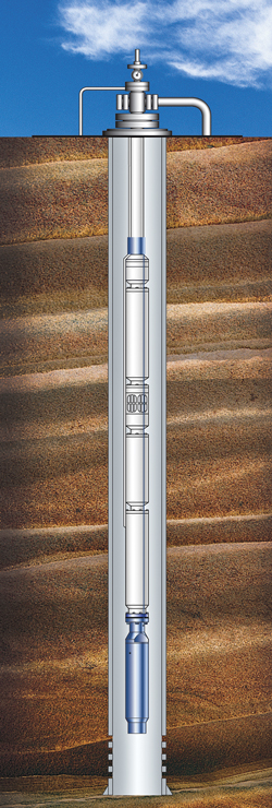 |
| Fig. 20. The Phoenix Multisensor digital well monitoring system is helpful in solving instability problems and improving well intervention planning. |
|
The new gauges are available in two configurations. The Type 0 configuration has a base gauge that fits the ESP motor, either directly or through a simple motor-base crossover. The monitoring system measures intake pressure and temperature, motor oil or motor winding temperature, vibration and current leakage.
The Type 1 configuration measures pump discharge pressure, which is used to evaluate pump performance, and provides all the measurements made by the Type 0 monitoring system. Using the pump discharge measurement, pressure across the pump can be calculated, and the points on the pump curve can be plotted. These values aid in diagnosing problems in the pump or elsewhere in the completion. The level of monitoring appropriate for each ESP completion can be selected.
Compatible with other monitoring and control technology, the new monitoring system is SCADA-system ready, with a remote terminal port and RS-232 and RS-485 ports for continuous data access. The unit, the controller, a surface choke assembly, computer software for data retrieval and a memory key, can all be combined with other equipment to achieve integrated monitoring and control.
GAS WELL DEWATERING
SuperFlow plunger addresses liquid loading early in well life. Shale plays are a game-changer for global gas producers. Horizontal drilling and hydraulic fracturing technologies have unlocked gas reserves previously off-limits to producers. In addition to drilling and completion innovations, new plunger lift technologies prove beneficial for many shale wells.
When downhole production rates approach the critical flowrate, liquid accumulated in the tubing impedes the flow of natural gas to the surface. Utilizing a plunger lift system can improve production, yet excessive shut-in times required by conventional plungers to reach the bottom of the tubing can dampen recovery rates. Because of the extended shut-in time associated with conventional plungers, operators typically install plunger lift systems in shale wells long after production has declined.
Minimal shut-in times allow substantially more plunger trips, removing production-impeding tubing liquid on each cycle. The SuperFlow plunger (Fig. 21) from Ferguson Beauregard promotes the addressing of liquid loading early in a well’s life, thus enhancing well performance. The plunger routinely demonstrates improved shale well production, long before surface conditions indicate critical flowrate is nearing. This plunger is offered in three standard tubing diameters, 2-3/8 in., 2-7/8 in. and 3 in.
 |
| Fig. 21. The SuperFlow plunger addresses liquid loading early in a well’s life to enhance performance. |
|
BEAM / ROD PUMPING
Cage insert promotes better flow and particulate handling. Harbison-Fischer has introduced the new patent-pending Tangentflow cage insert for insert guided cages. Advantages of this new insert include better flow characteristics, a better ball stop, enhanced particulate handling, and the same hardness, strength and corrosion resistance of existing hard-nickel alloy inserts. The top of the insert is machined in a fashion that cups the ball at the top of its travel. This prevents ball chatter, therefore reducing ball wear. The optimized Tangentflow fluid path reduces pressure drop and streamlines the fluid path while keeping particulates in suspension longer. These inserts are designed for API or alternate ball sizes and have the same ball race clearance as standard inserts.
Beam gas compressor offers longer stroke, helps marginal wells. The HyBGC beam gas compressor (Fig. 22) from Compressco can offer significant capital cost savings and better economics over traditional reciprocal compression units. It offers a longer stroke length than standard units and a simpler method of transferring energy to the compression cylinder. Its ability to provide the benefits of the beam gas compressor with the ease of operation provided by hydraulics allows for a great combination, when a pumping unit is not the answer. A proprietary control system allows the ease of one-touch operation to alter the strokes per minute, based on formation or tank battery needs, as well as providing basic alarm and shutdown features.
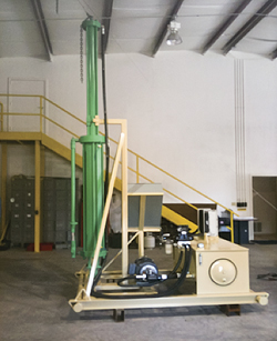 |
| Fig. 22. The HyBGC unit utilizes a longer stroke length than standard units and a simpler method of transferring energy to the compression cylinder. |
|
The HyBGC unit can make a marginal well profitable, push gas into sales lines, recover vapors from stock tanks and also operate at high temperatures, as in a steam flood. It is non-corrosive and not effected by H2S or CO2. The unit reduces gas pressure from the annulus and increases downhole pump efficiency. Problems with gas interference and gas locking of the pump are often minimized by this process (drawing gas and reducing the casing pressure on the annulus will cause more gas to break out of solution in the wellbore, where it will move up the casing to be removed by compression). Increasing the differential pressure at the bottom of the DHP forces the gas to choose to move along the avenue of lower pressure or up the annulus.
The unit’s control system is a sophisticated but user-friendly, totally electronic system. The control system is expandable, and has remote communication capabilities. All hydraulic system functions are monitored and controlled by this system. Among the system functions are stroke speed control, turn-around cushion and cooler fan on/off parameters, along with a manual stroke up/down feature. The LED control screen displays all hydraulic system functions in real time, making troubleshooting and diagnostics simple.
Infinitely variable transmission optimizes pumpjack operation. In a recent field evaluation, Turbo Trac’s Infinitely Variable Transmission (IVT) was applied to a pumpjack. It proved its worth, improving overall production revenue while decreasing operating problems and costs. The IVT is designed to provide torque and speed variation in an industrial system powered by electric motors, internal combustion engines or other prime movers. It functions similarly to a variable-speed (or frequency) drive (VSD or VFD) used with electric motors and also installed on pumpjacks. In oil well applications, the IVT can be applied when the prime mover is either an electric motor or casing gas-powered internal combustion engine.
The IVT that was evaluated is rated at 465 lb-ft of torque output (100 hp at 1,200 rpm input speed). This model is one of a family designed on a common chasis. The performance evaluation was conducted a various output speeds and loads dictated by well conditions. The IVT performed successfully at all speeds dictated by the rod pump controller, and all loads imparted by well conditions. Among the benefits demonstrated, the IVT allows sizing of the motor for operating load (not start-up load), thereby reducing installed horsepower by 25%. In addition, the IVT provides a full, variable-speed solution for pumpjacks. With the transmission set at zero output speed, the motor starts at “no load,” thus starting current is near operating current. This substantially reduces electricity demand charge while also reducing the impact on pumpjack components. In particular, the IVT can allow replacement of a 100-hp electric motor with a 75-hp unit, thereby saving the producer $900 annually in electricity demand charges.
One other major advantage that should be noted is the IVT’s ability to minimize potential damage to variable-speed solutions caused by lightning strikes. According to Turbo Trac, one lightning strike on a 100-hp VFD installation could cost as much as $25,000, while the cost to the IVT would only be about $2,000.
GENERAL
ZiLift, an Aberdeen-based provider of artificial lift solutions for the oil and gas industry, has received a growth capital investment of £4 million (US$7 million) from new and lead investor Energy Technology Ventures—a GE/NRG Energy/ConocoPhillips venture—and existing investors Energy Ventures, Chevron Technology Ventures, Viking Venture, Jebsen Asset Management and Investinor. ZiLift is developing innovative next-generation technologies for the global artificial lift market, estimated to be worth US$6 billion. Proceeds from this investment round will assist ZiLift in completing product development and achieving commercialization of its technologies.
Among the items being developed and tested are a rig-less solution, which will significantly reduce installation costs; state-of-the-art permanent magnet motors, with highest force density (flow/depth) and enhanced reliability; small-diameter pump motors that enable new options/configurations for artificial lift solutions; and integrated monitoring and control, to enable remote production optimization and autonomous system control.
ZiLift CEO Iain Maclean said, “Testing of our prototypes is now in its final stage, and we are currently planning to start field trials in the second half of 2012.” 
|
AUTHORS
|
 |
JAMES F. LEA teaches courses in artificial lift and production for Petroskills. He holds BS and MS degrees in mechanical engineering from the University of Arkansas and a PhD from Southern Methodist University. He worked for Sun Oil as a research engineer from 1970 to 1975, taught at the University of Arkansas from 1975 to 1978, was team leader of production optimization and artificial lift at Amoco EPTG from 1979 to 1999 and was chairman of Texas Tech University’s petroleum engineering department from 1999 to 2006. |
|
 |
HERALD W. WINKLER is former chairman and now a professor emeritus and research associate in Texas Tech University’s petroleum engineering department located in Lubbock, Texas. He also works as a consultant to the oil and gas industry in artificial lift, specializing in gas lift. |
|


.jpg)


