Floating gas liquefaction projects, FPSOs and gas monetization technologies are making strides in 2008.
David Wood, David Wood & Associates; and Saeid Mokhatab, Contributing Editor, LNG
Floating gas liquefaction has progressed from a technology with future potential, where it has resided for more than 20 years, to one with viable commercial projects now under construction. For a technology that has had such a long development period, FLNG has recently moved up the development agenda.
NEW FLOATING LNG SUPPLY CHAINS
The initial breakthrough came from the independent sector, not from the major oil companies. In June 2008, Flex LNG confirmed with its partners, Mitsubishi and Peak Petroleum, its intention to jointly develop and market the world’s first floating gas liquefaction (FLNG) project off Nigeria. Flex LNG also announced a second FLNG project offshore Papua New Guinea to develop, in partnership with Rift Oil, remote gas reserves recently discovered onshore. By the standards of the baseload gas liquefaction plants being built around the world, the Flex LNG projects involving gas Floating Production Storage and Offloading (LNG FPSO) vessels with throughput capacities of some 1.7 million tonnes per year (MMt/y) are relatively modest.
LARGE-SCALE FLNG: VISION EVOLVING
Shell, a major investor in FLNG research in recent decades, has, in the past, had several failed attempts to commercialize its larger-scale visions for the technology. However, in July 2008, Shell announced a tender for Front-End Engineering and Design (FEED) and engineering procurement and construction contracts for a 3.5-MMt/y capacity LNG FPSO, with a deck area of 1,500 ft by 250 ft to contain its proprietary liquefaction process technology. It is believed that Shell plans to deploy this vessel to develop its Prelude gas discovery-some 2 Tcf in reserves-in the Browse Basin of the Northwest Shelf offshore Australia.
One of the challenges of offshore liquefaction is coping with frequent interruptions due to weather. This leads to more-frequent startups in which the aluminum containment tubes of the Main Cryogenic Heat Exchangers (MCHEs) have to be cooled to below -160°C. Shell’s technology makes the cooldown process more efficient, placing less stress on the MCHE, maximizing output and minimizing the volume of gas flared during startup. Frequent manual cooldowns are likely to lead to more downtime and maintenance requirements in large-capacity MCHEs.
Shell’s approach is clearly focused on further developing its larger-scale double mixed-refrigerant technology. This technology improves liquefaction plant performance in extreme weather conditions by using a mixed refrigerant rather than propane in the initial cooling cycle. In very cold ambient winter temperatures, a different refrigerant composition is used from that deployed in warm summer conditions. Such benefits for FLNG would clearly depend on the project location, but the flexibility of operating conditions is a clear advantage for an LNG FPSO for potential deployment at several locations during its lifetime.
Shell is also developing a parallel mixed-refrigerant process in which gas flows through two parallel liquefaction cycles preceded by a common pre-cooling cycle. This configuration also improves flexibility and plant reliability since production can continue at about 60% capacity when one of the cycles is shut down for maintenance. This technology is attractive for large baseload liquefaction plants because it has the potential to boost the maximum capacity of a two-cycle single train to some 8 MMt/y and rival the three-cycle Air Products APX process. However, it is the flexibility that such technology developments bring that is potentially of benefit for FLNG.
For large gas fields remote from infrastructure, FLNG offers clear advantages. Inpex has announced plans to pursue a large-scale, $4 billion FLNG solution for its Masela Block in the Timor Sea, with the support of Indonesia’s BP Migas, rather than an alternative plan to build a pipeline to Australia.
Environmental concerns about damaging the Kimberley coastline in northwest Australia have also led environmental groups to support schemes being evaluated by Woodside and Shell to build a communal FLNG processing hub for Browse Basin gas field developments.
However, regional governments are more likely to be influenced by the significant long-term community investments, employment and local infrastructure benefits that a large onshore baseload liquefaction facility would bring to the area. It seems more likely that FLNG in Australia will be focused on the more isolated fields.
SMALL-SCALE FLNG: OPPORTUNITIES BECKONING
In contrast to the majors’ focus on new technology for large-scale FLNG projects, industry momentum has, in the past year, shifted toward proven simple technology configurations. The high prices of natural gas in recent years have stimulated smaller technology companies to partner with established marine engineering companies for vessel design and fabrication and with independent upstream companies holding stranded gas reserves of more modest scale.
There are clearly more opportunities to deploy these smaller, lower-tech/lower-cost technologies that fall mainly outside the majors’ scale of materiality for non-associated gas field developments. However, with no-flaring rules now a reality in many countries and gas flaring recognized as both environmentally and commercially unsound, major oil producers are also being forced to consider lower-tech solutions to commercialize the associated gas being produced from major oilfield developments.
Associated gas now holds more value and comes with more restrictions. Hence major producers in some countries (e.g., Angola, Nigeria) are looking toward small-scale FLNG (and other-see below) solutions for handling large volumes of associated gas in a cost-effective manner to secure regulatory approvals for major oilfield developments.
In addition to the Flex LNG projects, other alliances have announced progress with their own FLNG technologies in the past twelve months. These include: Höegh LNG, Aker, ABB and CB&I Lummus announcing their LNG FPSO (1.6 MMt/y capacity); SBM and Linde also working pre-FEED on an LNG FPSO (2.5 MMt/y); Teekay, Mustang and Samsung announcing that their LNG FPSO was to be classed by ABS; and Teekay announcing an upstream alliance with Gasol and Africa LNG to market its FLNG vessel in parts of West Africa. The industry is expecting these groups to follow Flex LNG and sanction firm vessel construction and gas field development projects in the near future.
FLEX LNG TECHNOLOGIES
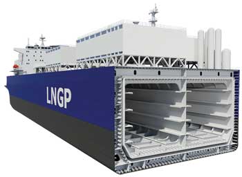
Flex LNG, formed in 2006, placed orders for some of its vessels in 2007. Its LNG Producer (LNGP) is a self-propelled FPSO combining proven technologies with sloshing-resistant self-supporting, prismatic, IMO Type B (SPB) containment systems retaining maximum deck space, dual nitrogen turbo-expander liquefaction technology, proven LNG transfer technology-marine loading arms, and a proven ship-to-ship mooring system.
Four LNGP hulls, each with a capacity of 6 million cu ft, are on order at Samsung Heavy Industries in Korea. These orders were placed from March 2007 to April 2008 for deliveries from December 2010 to March 2012. Each vessel has a nameplate liquefaction capacity of 1.7 MMt/y. The LNGP hull includes storage tanks, power generation, offloading equipment, accommodation, ship-board turret systems and all utilities necessary to support the topside installation. Each hull is reported by Flex LNG to cost $460 million.
The topside orders have yet to be placed, but the design cost is expected to fall within $550--$700 per tonne of liquefaction capacity. The topsides concept involves a generic liquefaction module and a field-specific feed gas-processing module to cope with variable feed gas qualities.
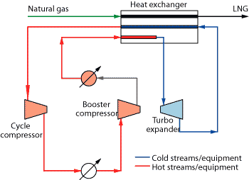
The vessels are designed to process some 230 MMcf per day of feed gas with some 12-15% feed-gas shrinkage. They will be equipped for side-by-side offloading with a disconnectable turret mooring system. Dual nitrogen expansion cycle (Fig. 1), selected for gas liquefaction, is proven technology used in small-scale onshore plants (e.g., peak-shaving facilities) and has the following additional offshore advantages: modularized, easy startup and shutdown, single phase/single component refrigerant, low equipment count with a small footprint and no hydrocarbon refrigerants.
 |
|
Fig. 1. The nitrogen turbo-expansion refrigeration cycle for the Flex LNG concept provides refrigeration by compression and expansion of a refrigerant that is kept in the gas phase throughout the entire system. The cycled refrigeration gas is first pre-cooled in the main heat exchanger with the returning cold gas. This temperature exchange takes place in the same heat exchanger that cools the process gas.
|
|
These benefits are well established but come at the price of lower efficiency than mixed-refrigerant processes.1 The SPB containment system (Fig. 2), out of favor for many years in conventional LNG ships, avoids the sloshing issues posed by membrane storage tanks and shortage of available deck space for processing equipment posed by spherical Moss-type tanks.
|
|
|
Fig. 2. SPB tank technology is used for the LNG Producer because it offers a sloshing-resistant containment system and maximizes flat deck space for topside equipment.
|
|
The June 2008 announcement that Flex LNG is to become an integrated equity partner in its Nigeria upstream project has added further credibility to its projects. Mitsubishi has also agreed to provide long-term LNG offtake terms for the 1.5 MMt/y capacity with LNG prices indexed to oil and gas benchmarks. Such arrangements should facilitate the equity and debt financing required for the Nigeria project to deliver its first cargo in 2011.
Gas reserves from the Peak Oil, operated offshore Nigeria license OML122, are expected to provide the required feed gas for some 15 years of operation for the LNGP vessel. Once reserves are exhausted, the vessel will be able to move to other fields with a reconfigured feed gas processing module.
In its Papua New Guinea project, Rift Oil will provide feed gas from onshore licenses PPL235 and PPL261 in remote western Papua New Guinea. That gas is to be piped to the FLNG vessel with annual production of 1.5 MMt/y targeted to start in 2012.
More gas reserves now seem likely in the region, but in several small accumulations, following the July 2008 Puk Puk-1 gas discovery drilled in PPL235, following the Douglas-1 gas discovery drilled in that license in 2007. Puk Puk-1 was targeting modest recoverable reserves for isolated locations of little more than 200 Bcf of gas. Rift Oil has a provisional agreement to supply the Alcan alumina plant at Gove in the Northern Territory of Australia with 40 Bcf per year of gas for 20 years.
In contrast to the Flex-Rift FLNG approach, two larger baseload gas liquefaction schemes in Papua New Guinea have progressed to FEED studies in 2008. The ExxonMobil-led PNG LNG involves a 6.3-MMt/y, $11 billion plant and pipeline. The 9-MMt/y Liquid Niugini plant (Interoil, Merrill Lynch and Pacific LNG) is the other land-based liquefaction plant in planning. Neither of these large-scale projects is expected to enter production until 2013 at the earliest, illustrating the potential shorter development time advantages of smaller offshore liquefaction schemes.
COMPETING LNG FPSOS
Several alliances are now pursuing quite distinctive designs and different liquefaction technologies.
Höegh LNG-led group plans to use CB&I Lummus’s NicheLNG dual turbo-expander liquefaction process and Aker’s SPB containment system providing a storage capacity of 6.7 million cu ft and a 1,000-ft deck length. In June 2008, Höegh LNG awarded FEED contracts to CB&I for the topside facilities and to Daewoo Shipbuilding & Marine Engineering for the hull, utilities and integration work for its FPSO project. A final investment decision is expected in first-quarter 2009, but no firm deployment project is announced.
The proposed project consists of a ship-shaped offshore classed structure with the capacity to treat and liquefy a wellstream of about 88.3 Bcf per year. This provides annual production of about 1.6 MMt of LNG and about 0.5 tonnes of LPG. In addition to LNG storage, the planned vessel will have storage capacity for some 1 MMcf of LPG/condensate. First delivery is unlikely before 2012.
SBM and Linde plan to use a multistage mixed-refrigerant liquefaction process, as deployed by Linde at the troubled Snohvit LNG plant in Norway, commissioned in late 2007, but are struggling to overcome some major technology problems and sustain full capacity. Their FLNG concept involves larger storage tank capacity than Flex LNG with 8.1 million cu ft, but also plans to use SPB-type LNG storage tanks. Japanese ship builder IHI is commissioned to design the hull.
The Teekay-Mustang-Samsung design involves Mustang’s proprietary LNG Smart liquefaction process in which all refrigeration is provided by the process fluid using turbo-expanders, and no refrigerant storage is required. The simplicity of the process suggests that it should be able to accommodate variable gas compositions and production rates, typical of associated gas from oil fields.
The process, for which little technical detail is available, should also be able to cope with the more-frequent shutdown/startup cycles to be expected offshore more easily than mixed-refrigerant processes. However, as with nitrogen refrigerants, those consisting primarily of methane are likely to sacrifice thermal efficiency in the liquefaction process. Initial design involves a combined storage capacity for LNG and LPG in excess of 7 million cu ft.
OTHER GAS MONETIZATION TECHNOLOGIES
Cryogenic LNG is not the only gas liquefaction technology to receive recent attention and investment. LNG Lite, Compressed Natural Gas (CNG) and small-scale, low-tech gas-to-liquids technologies report variable progress.
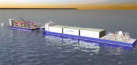
LNG Lite. SeaOne’s LNG Lite concept uses patented Compressed Gas Liquids (CGL) technology. In the CGL process, a hydrocarbon solvent is added to the natural gas stream after it is cleaned of impurities. Its effect is to cause the gas to liquefy when subjected to a temperature of -40°C and a pressure of 1,400 psi. This first phase of the LNG Lite system is accomplished on a loading barge moored at an offshore wellhead.
The conditioned natural gas stream is then piped aboard the CGL carrier (Fig. 3) in liquid form and stored in a bundled pipeline (42-in. carbon steel) containment system with a gas cargo volume of some 1.5 Bcf contained in 102 mi of coiled and bundled pipe. This transport system has some similarities with the coselle method of transporting CNG. To deliver its cargo the CGL carrier offloads to a transmission barge, which simply expands and separates the gases.
|
|
|
Fig. 3. Horizontal continuous pipe systems are nested as a cargo inside the cargo containment areas aboard a compressed gas liquid carrier that is part SeaOne’s LNG Lite Marine Gas Transportation System.
|
|
SeaOne compares the supply chain economics for a 3-Tcf gas field delivering 3 MMt/y for 10-15 years using LNG Lite favorably vs. conventional LNG.2 For a 2,000-mi supply chain employing 1.5-Bcf CGL carriers (about half the capacity of a standard-size LNG carrier) supported by one loading and one offloading barge, SeaOne estimate a total capital cost of $1.5-$2 billion ($0.75-$1.00 per MMcf) compared with a conventional LNG solution of $3.5-$4 billion ($1.75-$2.00 per MMcf).
Moreover, SeaOne claims that LNG Lite uses less than 60% of the energy that conventional LNG does and that there is zero shrinkage of the gas cargo during the transportation and unloading processes. Furthermore, SeaOne claims that LNG Lite uses 93% less energy per equivalent gas molecule delivered (gas and gas liquids) than conventional LNG does. CGL does provide smaller energy volume benefits than conventional LNG (i.e., some 620 cu ft of natural gas compressing to just 35 cu ft of cryogenic liquid). CGL appears to manage less than half of that volume benefit, but its cost savings, if achievable, should outweigh that limitation.
In 2007, ABS awarded Approval-In-Principle to the LNG Lite concept marine vessel, but projects using the concept are yet to be announced. Associated gas development projects in conjunction with NGL handling and transport from large offshore oil fields should be a potential market for this technology, in addition to competing against FLNG schemes for small to medium-scale non-associated gas field development opportunities.
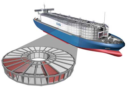
Compressed natural gas. CNG projects continue to elude the commercial breakthrough they require to unlock medium-distance or small-market (e.g., islands and cities isolated from energy infrastructure) supply chains, where the CNG concept appears to offer certain commercial advantages to LNG and pipeline solutions. However, in July 2008, Sea NG inaugurated its Gunsan fabrication site in South Korea for the fabrication of its patented Coselle CNG containment system, a precursor to building the first CNG ship in alliance with Marubeni and Teekay, Fig. 4.
|
|
|
Fig. 4. SeaNG plans to use the coselle gas containment technology and has obtained full classification approval from ABS for ship construction.
|
|
The coselle is a container that consists of 10.6 mi of small 6-in.-diameter steel pipe that has been coiled. Each coselle holds about 3 MMcf of natural gas. Its cost-effective design is viewed as a major advantage when competing with FLNG projects and with other CNG vessel designs. Large-diameter CNG bottles in the Votrans technology were previously proposed by EnerSea, which appears to be no closer to getting a marine CNG project sanctioned than it was in 2001. Sea NG’s ships, if ultimately built, will each be able to accommodate between 6 and 84 coselles stacked within a ship’s hold and connected using a simple manifold and control system.
CNG should be able to compete in isolated niche markets, but these markets seem reluctant to sanction untried technologies. In June 2008, Sea NG presented its case to the Mediterranean island of Cyprus claiming that CNG carries fewer environmental risks than LNG. Its case also emphasized that CNG does not need expensive terminals, is not a technically complicated system, and has flexibility in loading and unloading options, meaning that it could deliver gas to more than one power plant-options that are not available to LNG.
Cyprus is only a few hundred miles away from North African gas supplies (e.g., Egypt and Libya) but separated from them by deep water, which makes small-volume pipelines non-commercial. Such a situation, which is well within the supply chain length limitations of CNG, should favor the technology.
Gas-to-liquids. GTL has made some progress in recent years with the 34,000-bpd Oryx plant, commissioned in 2006 in Qatar, improving its efficiency. Shell’s Pearl 140,000-bpd GTL project in Qatar, which received final investment decision in early 2007, has been plagued by massive cost inflation since its FEED study ($6 billion to some $20 billion), which also resulted in ExxonMobil withdrawing from its proposed Palm GTL project in 2007.
Another GTL project dogged by cost overruns and time delays is the 34,000-bpd Escravos Phase-3 plant under construction by Chevron and Sasol since 2005, and not expected to deliver substantial product until 2010. In June 2008, the latest cost inflation estimated for that project, more than doubling original project costs to $6 billion, was the subject of a Nigerian Senate inquiry concerning its $2.9 billion share in the project costs.
Notwithstanding the high cost and complexity of these Fischer-Tropsch technologies, with oil prices still around $100 per bbl these plants remain economically attractive and will provide their owners with substantial profits on the premium-grade middle distillates, naphtha and waxes that they produce. The many patents for the technologies, held by a few major companies, and high costs are what prevent more FT-GTL plants being sanctioned around the world.
LOW-TECH GTL SOLUTIONS
As discussed above for LNG, small-scale low-tech GTL technologies being offered by smaller companies are also drawing more attention and offering additional technology competition to the same field development opportunities being targeted by small scale FLNG and CNG projects. One such technology being developed by CompactGTL uses a streamlined syngas-FT process module focusing on remote onshore and offshore opportunities to convert between 10 and 50 MMcfd of associated gas into 5,000 bpd of unfractionated syncrude.
This technology avoids the product fractionation and patented catalysts of larger baseload plants. It should appeal to large offshore oilfield developments to handle associated gas and prevent flaring.
In 2006, CompactGTL reached an agreement with Petrobras of Brazil to produce up to 20 bpd of syncrude at an onshore production facility. Petrobras is interested in proving such technology for deepwater offshore deployment on an FPSO vessel to avoid gas reinjection costs and add some 10% to the revenue stream of a volatile oil field. The concept has a number of other potential operational benefits: flexibility of throughput to match oil production profiles, scalable plant configuration, no oxygen requirement, negligible wastewater and no on-site catalyst handling.
The CompactGTL plant is being designed as a two-component module (syngas and FT components) that could be easily integrated in the topsides of an FPSO, as well as a stand-alone onshore facility. As an oil field’s production declines, surplus modules can be easily “switched off,” providing operating efficiencies and a reduction in operating costs for the FPSO.
Also, as the associated gas is converted to synthetic crude, it can be commingled with the crude oil produced from the field and transported to market by means of the existing oil transportation system. The syncrude can be marketed at refineries facilitating arbitrage more easily than for the natural gas products of FLNG and CNG.
Technologies to handle associated gas on a small scale have to be cheaper and lower-tech to be commercially viable. For example, the Gas Recycle Group in association with Russian company RussNeft is promoting a small gas processing module to extract and separate NGLs, particularly LPG and naphtha, from associated gas and, if appropriate, to manufacture methanol.
A pilot plant at Mokhtikovsky Field has demonstrated that it can convert, at very low cost, 700 MMcf per year of raw gas into 8,000 tonnes of LPG and naphtha. Such solutions are attracting interest from independent Russian, Caspian and West African onshore operators because they are now obliged to pay fines per unit volume of natural gas flared.
Vortex Oil is testing a magnetostriction GTL process for fast, low-tech, low-cost catalytic liquids production, applying a novel electromagnetic technology. The technology is undergoing pilot plant testing in 2008 and is said to be able to crack heavy crude oil and convert a range of feedstocks, including wood chips and syngas (derived from natural gas, coal or biomass), at low cost, to a variety of liquid fuels. Efficiency is likely to be low, but for small-scale onshore operations in remote locations this may be a more cost-effective option than paying fines for flaring or other alternatives.
Remote field operators have to evaluate whether synthetic crude and low-grade fuel products may be commercially more attractive to market than natural gas from their associated gas production. With high oil and refinery product prices, the answer is probably that small-scale GTL is more commercially viable in many cases for associated gas projects than FLNG, LNG-Lite and CNG.
GAS HYDRATES NOT YET FOR COMMERCIAL TRANSPORTATION
Research continues on the potential use of methane hydrates for gas transportation and storage. Feasibility studies conducted in Norway had shown that hydrate technology for large-scale and long-distance transport of natural gas would cost about one-quarter less than established LNG technologies.3 Laboratory tests have proved the concept of potentially storing natural gas in hydrates, but applications have not progressed beyond the laboratory stage because of complexities of the process, slow hydrate formation rates and costs. Methane is compressed about 160 times in a hydrate lattice (compared to some 600 times by LNG), but water forms some 85% of the gas hydrate by weight, adding to the transportation, storage and regasification costs. No projects are close to commercialization, but technological advances continue to be made-e.g., forming the hydrates from a surfactant solution-that may make this possible in the long term.4
Most ongoing gas hydrate research is focused on technologies to enable exploitation of the vast gas resources in Arctic onshore regions and on the deepwater continental slope locked up in hydrate reservoirs. That research is receiving major funding around the world, and much energy industry, government and academic attention. There remains a possibility that a spinoff from ongoing research may be a route to commercializing gas hydrate transportation technologies. In the meantime, industry has plenty to consider with diverse LNG, CNG and GTL technology options in the process of commercialization. 
LITERATURE CITED
1 Wood, D., Mokhatab, S. and M. J. Economides, “Offshore natural gas liquefaction process selection and development issues,” SPE 109522, presented at the SPE Annual Technical Conference and Exhibition, Anaheim, Calif., Nov. 11-14, 2007.
2 Ryan, P. and B. Hall, “Portable pipeline,” ABS Surveyor, Spring 2008, pp. 2-7.
3 Gudmundsson, J. S. and M. Mork, “Stranded gas to hydrate for storage and transport,” presented at the International Gas Research Conference Amsterdam, Nov. 5-8, 2001.
4 Rogers, R. E., Etheridge, J. A., Pearson, L. E., McCown, J. and K. Hogancamp, “Gas Hydrate Storage Process for Natural Gas,” GasTIPS, Winter 2005.
|
THE AUTHORS
|
| |
David Wood is an international energy consultant conducting project evaluation, research and training. He specializes in the integration of technical, economic, risk and strategic information to aid portfolio evaluation and management decisions and holds a PhD from Imperial College, London. Construction of numerical models for a wide range of energy-related topics, including project contracts, fiscal terms, economics, gas, LNG, GTL, portfolio and risk analysis, are key parts of his work. Please visit his website www.dwasolutions.com or contact him by email at dw@dwasolutions.com
|
|
| |
Saeid Mokhatab consults for a few companies and research institutes in the natural gas and LNG industry, worldwide. His areas of expertise include technical and commercial aspects learned while working in senior technical and managerial positions at several international gas-engineering projects as a solution integrator and key source of expertise.
|
|
|

