Electrophoretic migration enhances drilling fluid properties and performance and also reduces environmental impact.
Karen McCosh, Sarah Wood, M-I SWACO; and Gerry Meeten, Schlumberger Cambridge Research
Applying electrophoresis to drilling fluids aids the removal of solids and brine, positively impacting its physical properties by decreasing the density and viscosity with an increase in the relative oil content. This reduces the excessive dilution that can be associated with reconditioning drilling fluids and effectively extends the drilling fluid’s useful life. The waste disposal volumes and associated costs are also reduced. Therefore, this electrophoresis technology meets both operational and environmental goals.
After cuttings and fluids are removed from the borehole, a series of solids-control equipment is used to separate the cuttings from the fluid. The treated fluid is returned to the active drilling fluid system and recirculated back down the borehole.1 Since drilling fluids are used to drill multiple wells, fine (<5 µm) Low-Gravity Solids (LGS) build up because they cannot be removed by the separation equipment. Above 2-5% volume, the LGS can generate excessive low- and high-shear-rate viscosities, reduce drilling rates, increase stuck-pipe tendency and increase torque and drag.2
Drilling fluids are diluted to reduce the LGS concentration and reformulated back to the required properties, which is costly and increases the drilling fluid volume, which leads to storage, transportation and disposal issues. The environmental impact of continuously disposing of large fluid volumes must be addressed and disposal volumes reduced.
This article describes a method for invert-emulsion drilling fluid recycling. The method is based on the principle of electrophoretic movement of charged particles under the influence of an electric field, and is used to remove drilling fluid contaminants, to increase the effective fluid lifespan, and reduce the need for dilution and disposal.
ELECTROPHORESIS
Electrophoresis is the motion of charged, chemically identical molecules in a medium under the influence of an electric field.
The force, F, on a charged particle in an external electric field is proportional to the charge, q, of the particle and the electric field strength, E. This can be represented as:

If q is measured in Coulomb5 (C) and E is in V/m, F will be given in Newtons. However, the particle velocity depends also on particle properties, e.g., surface charge density and size, and on the properties of the solution through which it travels, e.g., frictional forces and viscosity. As the charged species migrate, they concentrate and form a deposit at one of the electrodes. The electrode’s charge, positive or negative, will indicate the species of particle forming the deposit. The quantity of deposit formed will not only depend on the migration rate and direction, but also on electrode geometry, area, collection time and temperature.
ELECTRIC FIELDS AND INVERT-EMULSION DRILLING FLUIDS
Voltage application to an invert emulsion is commonly used to determine the emulsion stability of the system, with a voltage being applied between two electrodes, 1.6 mm apart, immersed in the fluid.3 A typical breakdown field is 280 kV/m caused by the formation of continuous and electrically conductive particle chains between the electrodes.4 The electric fields used in electrophoretic separation of charged species from the invert fluids, typically 0.1-10 kV/m, are therefore much lower than the breakdown voltage field. Test equipment was developed that creates an electric field between two coaxial cylinders. Up to 440 V DC can be applied, so that the inner cylinder becomes negative with respect to the outer cylinder, creating a radial electric field between the electrodes and through the drilling fluid.
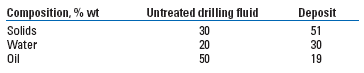
An electric field’s effect on an invert-emulsion drilling fluid with a density of 9.5 lb/gal and an oil/water ratio of 75:25 was examined. Over a 3-hr period, 440 V was applied to the system using the laboratory test cell, with the inner cylinder negative. Over this time, material concentrated and stuck to the inner cylinder to form a deposit, which could be removed from the test cell. Table 1 shows that the deposit contained a higher concentration of solids and water compared with the original drilling fluid, showing that under the electric field’s influence, both solids and brine droplets migrated toward the inner negative cylinder. Clay particles, present as drilled solids, and brine droplets possess charges that will allow migration under the influence of the electric field. Barite, barium sulphate, weighting material is inert and possesses no charge, but may become entrained in the deposit through co-migration with the other particles. Barite particles, as well as the clays and brine droplets, may also acquire charge from the emulsifiers and oil-wetting agents added to the drilling fluid system, enhancing migration.
| TABLE 1. Effect of voltage on drilling fluid composition: 400 V for 3-hr treatment |
 |
|
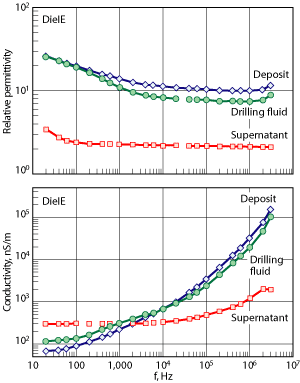
Dielectric measurements were made on a drilling fluid and on the deposit and oil-rich supernatant formed when 220 V was applied to the fluid for 1 hr. In these experiments, the invert-emulsion drilling fluid was based on internal olefin synthetic base fluid. The testing showed that the permittivity of the mud and deposit decreased with increasing frequency, but the permittivity of the deposit always exceeded that of the drilling fluid, Fig. 1. This is concordant with the deposit having the higher concentration of solids and adsorbed surfactant. The relative permittivities of both the drilling fluid and the deposit greatly exceed the permittivity of the supernatant because the latter contains no solids or absorbed surfactant. However, the supernatant permittivity is about 20-30, while 2 is a typical clean oil measurement. This is consistent with micelles of excess surfactant dissolved in the oil. In addition, the supernatant conductivity considerably exceeded that of both the drilling fluid and the deposit, Fig. 1.
 |
|
Fig. 1. Dependence of relative permittivity and conductivity on frequency for drilling fluid, deposit and supernatant.
|
|
At low frequencies, the deposit conductivity is less than that of the drilling fluid, probably owing to the tortuosity from ionic/micellar motion given by the extra solids in the deposit. For frequencies greater than 1 kHz, the mud and deposit conductivity exceeded that of the supernatant oil, probably owing to relaxation mechanisms such as charge-hopping. This suggests that the DC conduction, while forming the deposit, is due mainly to the transport of surfactant ions or micelles, rather than charge carried by clay particles. Thus, the dielectric data for drilling fluid, deposit and supernatant are compatible with the deposit having solids content greater than the fluid, and with conduction occurring mostly through the transport of ions or micelles in the electric field applied to the mud. These suggest that electrophoresis may occur because charged ions or micelles are attached to, or adsorbed on, the surface of the particles. In addition, the conductivity (s) data of Fig. 1 shows that for electric fields of very low or zero (DC) frequency, s is less than 100 nS/m, or 10-7 S/m, compared with typically 1 S/m for aqueous salt solutions. It is this small conductivity that allows the electrophoretic process to proceed with small current and, hence, a very small power requirement.
EFFECTS ON ELECTROPHORETIC SEPARATION
To understand the variables that affect migration and separation of solids and brine droplets from invert fluids in an electric field, a series of laboratory studies were conducted using drilling fluid contaminated with various chemical products. Each sample was treated with 440 V for 3 hr using the laboratory test cell, with the weight and composition of any deposit collected on the inner cylinder determined.
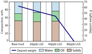
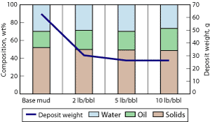
Effect of drill solids. Low-gravity solids are incorporated into mud systems during the drilling process, and eventually build up in the fluid. Hymod Prima clay and bentonite were added to the drilling fluid system to simulate these solids. After electrophoresis treatment, it was observed that increasing the solids content lowered the volume of deposit collected, Fig. 2. Increased drilling fluid viscosity may have hindered the migration of the charged species towards the electrode. The deposit had solids content consistently at approximately 50 wt%, Fig. 2. As solids content increased, oil content increased, which caused the deposit to become lubricious and unable to stick to the inner cylinder. Results suggest that solids travel faster to the electrode than the brine droplets, and/or that the large amount of solids hinder droplet migration.
 |
|
Fig. 2. The effect of increased LGS content on deposit formation and composition: 440 V for 3-hr treatment with lab scale test equipment.
|
|
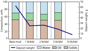
Effect of emulsifiers. Primary emulsifiers are strong surfactants used in drilling fluid to stabilize the water-in-oil emulsion. Secondary emulsifiers act as oil-wetting agents, and contribute to other drilling fluid properties such as filtration control. The surfactant molecules act at the surfaces of the brine droplets and solids particles, and therefore may affect the migration of these in an electric field. This was suggested by the dielectric measurements previously discussed.
Both primary and secondary emulsifier products at concentrations up to 20 lb/bbl were added to a standard drilling fluid, resulting in a decreased amount of deposit formed at the inner cylinder and a stiffer and stickier deposit. The final composition of the deposit remained constant in terms of solids, oil and water content, Figs. 3 and 4. The results suggest that the emulsifiers slowed migration rate of the particles or droplets, but the high concentration of the emulsifier in the deposit resulted in a change in consistency.
 |
|
Fig. 3. The effect of primary emulsifier concentration on deposit formation and composition: 440 V for 3-hr treatment with lab-scale test equipment.
|
|
 |
|
Fig. 4. The effect of secondary emulsifier concentration on deposit formation and composition: 440 V for 3-hr treatment with lab-scale test equipment.
|
|
Effect of drilling fluid type. Compositions of invert drilling fluids and specific chemical additives used to achieve the required properties vary greatly. Two alternate drilling-fluid systems were tested to determine the effect of the electric field. The first fluid was based on a synthetic internal olefin, and the other was a specialty fluid based on mineral oil. Both fluids were tested using the laboratory coaxial cylinder test cell, and it was found that application of 440 V to the cylinders resulted in a deposit collected against the positive outer cylinder surface. Voltage polarity reversal, with the internal electrode charged positive, allowed the deposit to be collected on the inner electrode surface. Therefore, the alternative emulsifier chemistry impacted the migration of species in the electric field, causing the brine droplets and solids to travel in the opposite direction to that previously observed.
ELECTROPHORETIC SEPARATION APPLICATION
To determine the effect of electrophoresis on drilling fluid properties, a pilot-scale unit was designed and built. The pilot unit was used to determine the optimal operating conditions for treatment of invert drilling fluids, and the effect of collection interval, voltage and treatment duration.
Effect of increased deposit collection interval. When operating the electrophoresis unit, the concentrated deposit can be collected at any point during the treatment cycle and multiple collection runs can be included. The benefit of increasing time between collections has been shown through tests where drilling fluid was treated for 4 hr at 440 V. In discrete runs, deposit was collected every 30 min., every hour, every 2 hr and once after 4 hr.
As the interval between collection runs increased from 30 min. to 4 hr, the volume of deposit collected decreased, Fig. 5. As the collection interval increased, the volume of additional solids and water in the deposit increased, and the volume of whole fluid transfer decreased. Therefore, longer static time results in a lower volume of deposit collected, but a faster treatment of the drilling fluid to decrease solids and water content.
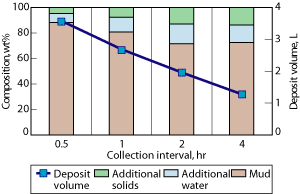 |
|
Fig. 5. Effect of collection interval on deposit volume and composition: 440 V for 4-hr treatment using the pilot unit.
|
|
Effect of increasing voltage. An increase in voltage applied to the collecting electrode should increase migration velocity of charged species, giving faster treatment rates and a greater deposit buildup. Tests over 4 hr, with the voltage increasing from 440 to 3,000 V, showed that the total deposit weight collected increased approximately linearly with voltage, Fig. 6. The oil/water ratio of the deposit decreased from 77:23 to 50:50 as the voltage increased. Therefore, the higher the voltage, the better the solids and brine removal performance to return the drilling fluid to acceptable properties.
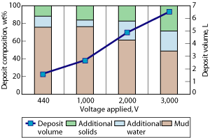 |
|
Fig. 6. Effect of voltage on deposit volume and composition: 4-hr treatment using the pilot unit.
|
|
Effect of treatment time. Increasing the length of time over which voltage is applied should allow a greater process time and greater concentration of solids and water at the collecting electrode. With 3,000 V applied, the total treatment time was increased from 1 to 8 hr. The volume of the deposit increased, with all deposits showing concentration of water and solids compared to the original drilling fluid.
The optimum treatment length ensures a low oil removal (the valuable component) and the deposit with maximum solids and water concentration. After 8 hr, 9.5 L of deposit was collected, which represented 30% of the total drilling fluid being treated, Fig. 7. Approximately 50% of the solids in the fluid was collected in the deposit, with only 14% of the available oil removed. Qualitatively, the deposit collected after 8 hr static at 3,000 V was much deeper on the drum (30-40 mm) and had a thick and sticky consistency.
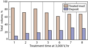 |
|
Fig. 7. Effect of treatment time on deposit recovery: 3,000 V using the pilot unit.
|
|
Treated mud properties. The testing on the pilot unit has shown that a long collection interval and treatment time with a high voltage are optimal. Therefore testing at 3,000 V was applied to the inner electrode, over an 8-hr period, with one deposit collection cycle used to define the effect on the properties of the treated drilling fluid. The deposit removed was heavy due to a large quantity of solids, and the deposit also contained a large quantity of water. The deposit constituted 30% of the drilling fluid volume and therefore 70% was recovered as treated fluid. In this treated fluid, the water and solids content was decreased to almost half of that present in the original system, while the valuable oil component was recovered at 80%. This translates to the recovery of a drilling fluid with lower density, increased oil/water ratio and a lower viscosity profile. In the example shown, Table 2, the density was reduced from 12 lb/gal to 9.1 lb/gal, the total solids content decreased from 23 to 13.5% and the oil/water ratio increased from 77:32 to 88:12, all resulting in a thinning of the fluid and a decrease in both the plastic viscosity and yield point.
| TABLE 2. Drilling fluid properties before and after electrophoresis treatment: 3,000 V for 8-hr treatment |
 |
|
FULL SCALE ELECTROPHORESIS TREATMENT
To treat larger volumes on a commercial scale, a standard equipment offering was designed. The unit is capable of treating approximately 650 L of fluid per batch. Treatment using this unit was demonstrated for a fluid containing 14% total solids. This fluid was treated for 8 hr at 900 V. Total solids content was reduced from 14 to 10%. A corresponding reduction in mud weight from 11 lb/gal to 10.3 lb/gal was measured. Removal of the brine phase increased the oil/water ratio from 58:42 to 66:34. During the process 32% of the original fluid volume was lost with the deposit, but 81% of the valuable oil component was retained in the processed drilling fluid.
ENVIRONMENTAL BENEFITS
The buildup of LGS in the drilling fluid is treated typically by dilution with fresh drilling fluid, such that the concentration is reduced and is no longer detrimental to the fluid performance. This is not only a costly exercise, but also generates supplementary volumes that have to be stored and disposed. Application of the electrophoresis technology to reduce the concentrations of solids (including LGS) and water in the drilling fluid results in improved properties, which will have a positive impact on the drilling operations, increasing the drilling rate and reducing the non-productive time. Fluids that were destined for disposal can now be economically treated and reused with only a fraction being sent for final disposal and without the need for excessive dilution. This will reduce cost, energy consumption, disposal volume and storage pressure.
Therefore, the electrophoresis technology can be used to reduce the total volume of waste generated and can increase the drilling fluid lifespan allowing reuse, with the valuable components recycled.
CONCLUSIONS
Use of an electric field allows solids and brine droplets to migrate and concentrate as a deposit that can be removed from the system. Longer treatment times, long collection intervals and high voltage improve the deposit’s quality and quantity. Treatment results in a decrease of the drilling fluid density and viscosity with an increase in the oil/water ratio, which reduces the excessive dilution associated with reconditioning drilling fluids. The waste disposal volumes and associated costs are also reduced. 
LITERATURE CITED
1 Darley, H. C. H. and G. R. Gray, Composition and Properties of Drilling and Completion Fluids, 5th ed., Gulf Professional Publishing, Oxford, UK, 1988.
2 AMSE Shale Shaker Committee, Drilling Fluids Processing Handbook, Gulf Professional Publishing, Oxford, UK, Ch. 2.
3 “API RP13B-2: Recommended practices for field testing oil-based drilling fluids,” 4th ed., API, 2005.
4 Growcock F. B., Ellis C. F., Schmidt D. D. and J. J. Azar, “Electrical Stability and Oil Wetness of Oil-Based Muds.” SPE 20435 presented at the SPE Annual Technical Conference and Exhibition, New Orleans, Sept. 23-26, 1990.
|
THE AUTHORS
|
|
|
Karen McCosh is technical manager, research development and engineering, for M-I SWACO. She has 12 years of experience in the oil and gas industry and manages a research department focused on the development of new technologies, processes and systems for the treatment of oilfield waste. She holds a BS in applied biosciences and chemistry from the Robert Gordon University in Aberdeen, UK.
|
|
|
|
Sarah Wood is a development engineer, research development and engineering, for M-I SWACO. She has five years of experience in the oil and gas industry and provides chemical engineering support for the development and testing of new technologies for waste treatment. She holds a bachelor’s degree in chemical engineering from the University of Edinburgh.
|
|
| |
Gerry Meeten is a principle research scientist at Schlumberger Cambridge Research Center in the UK. His primary focus is investigating many aspects of the physical behavior of colloidal and granular materials and processes, particularly those related to complex fluids and soft solids.
|
|
|


