Protecting the Environment
New type of water separator could help fill multiple oilfield needs
It is lightweight, is simple in design, is compact and has high throughput: What more do you want? But then, how well does it work?
Perry A. Fischer, Editor
In mature producing regions such as the continental US, it is estimated that more than 10 barrels of water are produced for every barrel of oil. A new separator technology is making its way into oilfield markets. Called the Voraxial Separator, it is a scalable liquid/ liquid, liquid/ solids and liquid/ liquid/ solids separator. It reduces the time, energy, space and cost needed to separate contaminants from the primary liquid. This article discusses how it works, and lists test data and experience to date.
THE TECHNOLOGY
It is not a production separator in the usual sense, but it is also more than just a water polisher. In general, when used in an oilfield production setup, present models are designed for use after a production separator or simple gas/ liquid knockout, in place of skimmers, flotation cells and similar water processing for re-injection or for produced water disposal overboard.
The new separator is scalable in nature and, although just one is generally sufficient, its small size could allow two of the devices (in series) to handle almost any separation need, possibly even primary production separation, depending on the well fluid profile.
The novel separator is a continuous-flow turbo machine that produces a high centrifugal force to separate liquid mixtures, or a combination of liquids and solids, by their specific gravity. At the inlet sits a motor-driven separator impeller, which is a low-shear device that creates a vortex flowing through the separator. High “g” centrifugal force – as much as 1,000 g – pushes heavier materials to the outside of the vortex, while lighter materials form a central core in the vortex. A special manifold at the outlet of the separation chamber collects the separated streams, Fig. 1.
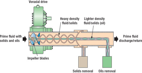 |
Fig. 1. Separation principle: shown is three-way, liquid/ liquid/ solid separation. Two-way, liquid/ liquid or liquid/ solid separation can also be configured.
|
|
A Model 4000 mounted atop a Model 2000 separator is shown in Fig. 2, complete with motor, electrical control, impeller housing, separation chamber and exit manifold, separating oil from water with a fully developed vortex. The core of the vortex, comprising separated oil, runs from the impeller housing to the Light Density Manifold. A vortex of red transmission fluid is shown in a clear pipe in Fig. 3. As can be seen, the separator is very compact. The energy required to operate the new separator is very low compared to centrifugal devices, especially at higher flowrates, where the energy requirement can differ by more than 10 times for a given flow. Table 1 gives flowrates, energy requirements and specifications for various models.
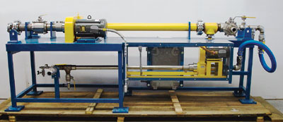 |
Fig. 2. A 4-in. (10-hp explosion-proof motor) in series with a 2-in. (3-hp motor), below table, as used offshore California. Control panel is in center.
|
|
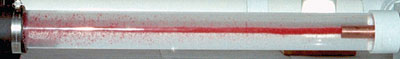 |
Fig. 3. A clear section of pipe with a vortex of red automatic transmission fluid formed in its center. Take-off is at right.
|
|
Liquid/ liquid separation. To document performance of the new separator, an independent consultant (Dr. Jeffrey S. Tennant of Florida Atlantic University) was contracted to test a 2-in.-ID unit. Test objectives were to determine the maximum oil/ water separation capability in the mode of producing oil-free water, and to determine pump performance.
The test report concluded: “The Voraxial Separator operates in its pumping mode in a manner comparable to any axial flow machine. It has the inherent advantage, however, of not requiring the flow to turn through an elbow, which is usually needed to accommodate the drive shaft for the impeller, and there is no need for shaft-bearing supports to interrupt the flow. Additionally, with the open center of the impeller, the machine should be much less likely to clog than conventional axial flow pump designs.” The oil/ water separation data for the 2-in. unit, as reported by Tennant, is shown in Table 2.
The report concludes that: “kerosene and water mixtures... (with) the clean-side water flows representing 94% of the flow, showed an average of 1.2 ppm of oil contamination after a single pass through the machine with a flow rate of 25 gpm (36,000 gpd). Several readings in the data set showed less than 1.0 ppm. This level of separation is only available in large centrifuges. For heavier oils (s.g. 0.85) the machine is effective and came very close to the performance value of 15 ppm (VAS was 17.3 on ATF). An optimized effort with those oils would likely produce less than 15 ppm in the outflow.”
Liquid/ solids separation. The new separator has been tested extensively for the separation of solids in water. A wide variety of solids has been tested, including solids heavier than water and solids lighter than water. The solids tested include municipal sewage solids, sand (heavy, fine and very fine), wastewater treatment sludge, mining wastes, chemical process wastes, metal finishing wastes and various other solid wastes. The separator exhibited excellent sand separation. Data collected in-house for the separation of fine sand and water is shown in Table 3.
APPLICATIONS
Because of its ability to treat liquid/ liquid, liquid/ solids, and liquid/ liquid/ solids wastewater streams, there is a wide range of applications for the novel separator. The company that owns and manufactures the separator is Enviro Voraxial Technology, Inc. (EVTN), a publicly held firm out of Ft. Lauderdale, Florida. Because of its location, far removed from the oilpatch, the company has not spent much time marketing to oil companies.
However, Shell Technology Ventures saw sufficient merit to invite the company to share its booth at this year’s SPE/ IADC 2005 Drilling Conference and Exhibition in Amsterdam. Since then, in addition to various stormwater and waste streams, inquiries for oilfield applications have climbed considerably. EVTN says that virtually every major oil company has expressed interest. These applications include:
- Management of offshore oil exploration/ drilling/ testing wastewater
- Treatment of oilfield production wastewaters
- Oil spills
- Ship ballast water treatment
- Ship bilge water treatment
- Treatment of wastewaters from dredging operations.
Offshore produced water. The new separation technology was tested in late April 2005 on Gail platform, which sits 10 mi offshore California in 739 ft of water and is operated by Venoco. It has produced over 30 million bbl of oil and 84 Bcf of gas. The test was a field test to process water from the sour production separator, Fig. 4. For this test, two separators were used in series. This configuration allowed for the cleaned stream from the 4-in. separator to be polished by the 2 in. separator.
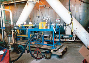 |
Fig. 4. The 4-in./2-in. separator in a test on Gail platform, offshore California, with personnel from Shell and EVTN in the background.
|
|
A hydrostatic test was performed on this configuration prior to shipment offshore. The unit was pressurized to 120 psig and monitored. During the test, a small leak in the seals occurred and the unit pressure dropped from 120 psig to 118 psig over the eight-hour test. The end pressure was about 1.5 times the intended design pressure (75 psi), but the unit was nonetheless accepted for operation offshore. The small leak, which continued throughout the production test, ultimately resulted in mechanical problems that prematurely terminated the testing. This could have been easily avoided by using equipment with higher pressure ratings. Nevertheless, important test data was gathered.
At the start of testing, the flowrate to the duplex arrangement was adjusted down to provide a flowrate of about 65 gpm – mid range for the 2-in. model, but well below the nominal flow for the 4-in. model. Produced water fed to the 4-in. separator was at 180°F. With the flows stabilized, samples were collected from the 2-in. and 4-in. sample ports to check the separation performance. The samples showed the separators were performing well.
The samples were sent to Capco Analytical Services, Inc., in Ventura, California for analysis. The sample from the Major Manifold (outermost region), i.e., the “cleaned” water, measured less than 20 ppm oil. Most of the sample collected from the Light Manifold (central flow region) coated the container with oil and was not measured. Measuring just the watery part of this sample, dissolved or dispersed oil measured 77 ppm. Estimating visually, total oil concentration in this sample was, most likely, over 10,000 ppm (> 1%).
As this goes to press, the company is deploying one of its 2-in. separators to an oil production facility in New Mexico for a produced water (oil/water) separation application, as well as to China’s CNOOC, for use separating oil and water on an offshore oil platform.
Oilfield saltwater injection. This operator had a long history of oil carryover problems to the saltwater injection tank and water injection wells. This mature field produces 670 bopd and 72,000 bwpd through four 10-ft by 30-ft free water knockouts. The water is dumped to 1,000 bbl and 2,000 bbl water tanks.
Oil carryover to the saltwater tanks can be as high as 1,000 ppm and has averaged 700 ppm over the last two years. Oil skimming operations with a tank truck on a weekly basis captured about 70% of that oil carryover, leaving 30% (200 ppm) to depart the plant and to enter the injection system. This oil carryover at the saltwater injection plant (SWIP) raised the downhole failure rate to 0.69 failures/ well/ year, which was unacceptable. Furthermore, this carryover resulted in a conservative 12 bopd of saleable oil lost to the company, which represents a significant amount of money at today’s prices.
Several chemical programs were implemented in an effort to reduce oil carryover while maintaining good corrosion protection. These two goals, taken together, were not cheap and not always optimal. The well failure rate jumped to 0.80 failures/ well/ year in the 3rd quarter 2003 and jumped again to a 0.92 average for year-end 2003.
A detailed review of all aspects of the cost of operation at the SWIP was undertaken. The consensus opinion reached between EVTN and the customer was that installation of an 8-in. Voraxial Separator 2,500 gpm and reversion to the original, effective, corrosion-inhibition program would recover over 12 bopd, reduce chemical cost and reduce down-hole failure.
The cost of monthly skimming operations could be avoided, reduced chemical use, fewer well failures and their associated costs, all pointed to a cost-effective solution. Even if based on only $28 oil, the cost analysis showed a two-year payback on the cost and operation of the new separator, and very favorable positive cashflow thereafter.
Unfortunately, despite the positive, detailed cost analysis, the operator did not implement the system for reasons unknown, stating that, he preferred to be in third place when it came to trying out new technology.
More important, the device becomes immediately useful and economic when produced water rates and oil carryover are both high. To that end, there has been keen interest in using the technology to reduce/ reclaim oil carryover in produced water re-injection on an Alaskan North Slope field, where produced water rates can be as high as 275,000 bpd, with 500 to 1,500 ppm oil. That’s about 8,000 gpm.
Using the new technology would result in an additional 200 bopd. In a situation such as this, the high throughput and good polishing properties of the device can reduce the payback period to less than a year.
Oil spill cleanup. The State of Alaska’s Department of Environmental Conservation purchased a unit for its Division of Spill Prevention and Response, which is charged with providing the State’s response to spills of oil and other hazardous material. The light weight, portability and high throughput were positive factors in selecting the separator for oil spill cleanup use.
Wastewater. At a wastewater treatment facility in Hillsboro County, Florida, 21 performance tests, two to six hours each, were carried out on a headworks (raw, inlet) waste stream during the first half of 2004. Most of the solids removed were similar to “sugar” sand, not unlike some downhole matrices that, unfortunately, sometimes get produced and end up in oilfield production separators. About half of the grit in the stream was less than 150 microns, and 15% was less than 100 microns.
A slightly more specialized device (model 4000GS), optimized for grit separation, was used. As expected, the best removal occurred at the highest rpm (3,500), with only 5% of the flow diverted with the separated sand. The overall efficiency at that rpm was 81 – 89% sand separation (by weight) for the entire range of particle sizes. For particles in the 150 to 250 micron size, separation efficiency was 85 – 95%. For 45 to 75 micron particles, efficiency was 66 – 84%.
CONCLUSION
The new technology’s performance and properties make it an efficient liquid/ liquid, liquid/ solids, and liquid/ liquid/ solids separator. Accordingly, it is receiving increasing support from various government agencies and private industry. The separator has important properties that include: scalability, very high throughput volumes, reasonably low energy requirements, light weight, compact, and an open impeller with low-shear performance, which makes it unlikely to clog.
Given the company’s location and recent efforts to market to the oilpatch, it will be up to the recent buyers of this technology to report to the rest of the oilpatch just how well the technology is working for them. 
ACKNOWLEDGMENT
This article is based in part on a paper by Dr. Daniel Samela, a consulting engineer with Enviro Voraxial Technology, Inc., various project documents and test data provided by the company, as well as conversations with John DiBella, vice president of the company, whom the author thanks.
|