Exploration
What’s new in seismic sensor technology
Four remarkable seismic sensor packages point toward an exciting future of lower costs and higher quality data
Perry A. Fischer, Editor
These days, you often hear that seismic is a commodity, that all traces are created equal. Price is all that matters. Of course, price does matter, certainly more than most contractors and equipment providers would like. But, in reality, there remains a formidable challenge for data providers: increase the quality of seismic data through intensive research and development while consistently lowering costs.
Considerable disagreement exists on how to meet this challenge. For example, at a recent conference, one speaker commented that he doubted if there would ever be a worthwhile fiber optic sensor developed. While many would disagree, including this writer and the US Navy, it exemplifies the range of opinions. Other issues include: achieving the lowest possible power requirements for certain applications; meeting high temperature and pressure requirements for wellbore installations; ensuring long lifetimes for permanent installations, whether on the seafloor or in the wellbore; ruggedness with less weight; ease of orienting multicomponent systems; improving vector fidelity; and eliminating noise.
What follows are systems that are in varying stages of development and commercialization. In most cases, the information derives from the vendors themselves. Not all sensors are appropriate for every application. This article is, therefore, best used as a guide for further research.
Sabeus
With fiber optic sensors that are made using Fiber Bragg Gratings (FBGs), the same fiber acts as the sensor, provides the telemetry path and allows multiplexing. As the name implies, an FBG is an optical grating imprinted into the core of the fiber using a laser. Each grating consists of periodic variations in the speed of light over approximately a half-inch section of the fiber. The grating selectively reflects a specific wavelength of light, allowing the remainder of the light to pass through unimpeded, depending upon the periodicity (spacing) of the gratings. Changes in temperature, pressure, strain and vibration at the grating will affect its periodicity, and thereby its reflected wavelength. Many gratings can be placed on a single fiber. A Bragg grating can be considered a universal transducer, in that any strain across it results in a shift in wavelength of the narrow light pulse, which can be measured. By slight variations in the precise geometry of the inner-core imprint, the narrow, diffracted wavelengths, representing many sensors, can be multiplexed up a common fiber. A small amount of light is reflected back to the surface from each FBG sensor, most of it is transmitted, able to be used in another FBG.
Until now, FBG imprinting required stripping and recoating the fiber, which increases manufacturing costs and degrades the fiber’s tensile strength. Sabeus developed a novel, proprietary process that eliminates the stripping/recoating steps. This directly translates to higher reliability and the ability to reliably manufacture and wind continuous fiber sensor arrays for a small fraction of the cost of conventional electronic-based sensor arrays.
These low-cost, completely passive optical arrays can be permanently installed on the ocean bottom, down a borehole or on land. The only electricity used is at the surface, Fig. 1. The surface electronics include a laser source with a phase modulator/pulse generator for launching light down the fiber. Receiver electronics use a multi-channel, Time Division Multiplexing/ Wavelength Division Multiplexing (TDM/WDM) interferometric interrogator that is scalable to thousands of sensor channels. The interrogator is based on the latest US Navy technology that is being transferred to Sabeus. The Navy has already capitalized on fiber sensor technology with multi-thousand channel systems for its newest nuclear attack submarines and for ocean bottom surveillance arrays.
 |
Fig. 1. First, a modulated light pulse is sent down the fiber. Second, any FBGs encountered act as partial reflectors. Next, as each pulse passes through an FBG, it undergoes a phase shift based on acoustic signal. Last, multiple return pulses are processed at the surface and converted to digital electrical signal.
|
|
The two major advantages of this fiber optic system are the elimination of electronics at the sensor end and a dramatic reduction in cost. The company estimates that the fiber system costs about half of a conventional electronic system. However, unlike conventional systems, most of the cost is at the surface, which means that for 4D surveys, costs could be reduced by half again if surface equipment is shared across multiple acquisitions/platforms.
Sabeus has developed a proprietary linear, flexible fiber optic hydrophone array specifically designed for seismic OBC and streamer applications, Fig. 2. This hydrophone array can be made in continuous sections of hundreds of meters. For streamer applications, a special low-shear material is applied over the core to isolate shear noise, eliminating the need for oil filling. The protective outer elastomeric cover is a tough, low-noise urethane-based material suitable for over five years of operation in an undersea environment, Fig. 3.
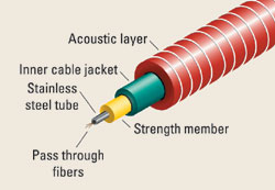 |
Fig. 2. Inner core composition of continuous fiber sensor cable prototype. FBGs are wrapped around the resilient acoustic material.
|
|
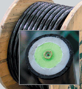 |
Fig. 3. For streamer applications, a special, tough urethane-based elastomeric material is applied over the core to isolate shear noise, eliminating the need for oil filling.
|
|
Short sections of the Continuous Acoustic Sensor (CAS) concept arrays were tested at the US Navy’s hydrophone calibration facility in San Diego. The sensor scale factor (i.e., acoustic sensitivity) and frequency response were measured in a large calibration pool. Results showed that system noise performance matched design predictions, demonstrating performance as good as, or better than, typical conventional streamers and OBCs, Fig. 4. If desired, performance can easily be improved or frequency response changed by modifying the fiber winding pitch and/or acoustic-layer material choice.
 |
Fig. 4. Sensor data from Navy calibration facility.
|
|
Weatherford
Through its acquisition of the Optical Sensing System Division of CiDRA in late 2001, Weatherford has been field testing a new seismic system that has been under development for four years. The system uses conventionally written fiber-Bragg gratings (FBGs) in uniquely designed optical accelerometers. In this application, the Bragg gratings are isolated from direct strain. Rather, their reflected wavelengths define a short length of fiber between two FBGs, which is exposed to strain via a moving mass; this arrangement acts as an interferometer, which is extremely sensitive. The strain in this case is proportional to the vibration caused by a sound wave. The sensors can be orthogonally arranged to form a three-component sensor package. The company would not release a schematic or more details concerning the mechanism of sensing, but Table 1 shows some preliminary specifications.
 |
The new sensors have been undergoing field testing with the help of Optoplan, a Weatherford subsidiary that led the design qualification and installation, plus the support of a Norwegian Demo 2000 Project, comprising oil company sponsors Total, Statoil, BP and Norsk Hydro. Designed specifically for permanent downhole installation, a multi-station, multi-component system was deployed for the purpose of conducting time-lapse (4D) seismic reservoir imaging and monitoring in a well at the Izaute gas storage field in southwestern France. Two types of permanent seismic surveys are being conducted: two, repeat walkaway VSPs, and extended microseismic monitoring. Feasibility studies previously completed at Izaute using conventional wireline tools demonstrated the ability to map the gas/water contact using VSP and to potentially correlate microseismic events to gas injection and production activity.
The prototype system comprised five 3C stations, deployed above the reservoir for walkaway VSP imaging, of which two will be active during the ongoing microseismic monitoring survey as well. A sixth, single 3C station was deployed near the reservoir solely for microseismic monitoring. Each 3C sensor station was deployed on the outside of 4-in. production tubing with a custom-designed device that independently couples the sensors to the casing and substantially decouples the sensor package from the production tubing and from cable-borne noise, Fig. 5. This completion design (Fig. 6) allows easy access through the tubing to the reservoir for logging tools, as is required on a regular basis. Fiber optic 1/4-in. cabling connects the seismic array to the surface and links the sensor stations.
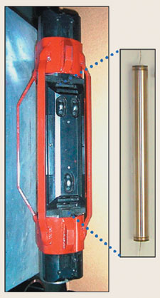 |
Fig. 5. A fiber optic sensor station: 3C accelerometer (right), production tubing carrier (left).
|
|
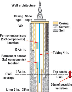 |
Fig. 6. Schematic of the Izaute well-monitoring field test.
|
|
Preliminary results are in, and they confirm that the company’s fiber optic-based accelerometer system is a viable alternative to conventional seismic sensor systems, with the added benefit of not requiring any electricity downhole. The data showed good correlation between the fiber optic sensor data and conventional surface seismic, as well as wireline VSP, Fig. 7. Further VSP tests and microseismic monitoring are planned, and the company plans to offer the system commercially later this year.
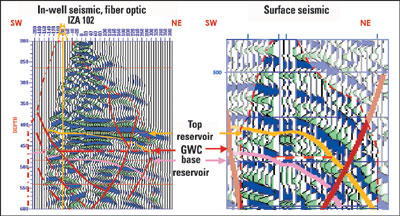 |
Fig 7. Results at Izaute: walkaway VSP from new fiber optic system (left), conventional surface seismic (right).
|
|
Sercel
Sercel has a new digital sensor that is the result of an industrial collaboration begun in 1995 between: LETI, a leading European laboratory in the field of micro-technologies, for R&D; TRONIC’S Microsystems for manufacture; and Sercel for specifications and tests. It is designed to be fully compatible with the company’s well known 408UL system.
When the 408UL was introduced, the concept of integrating the station electronics (FDU) with the cables into a user-defined module (Link), which could be handled in the most efficient way for any particular operation, represented a new concept in geophysical recording systems. In typical use, the Link’s analog sensor strings are connected to the integrated electronics, making the sensor a separate unit to handle, logistically. FDU design included options for a single sensor, whether 3C or 1C, to be integrated within the FDU, thereby becoming a part of the Link and allowing the electronics and the sensors to be handled as one unit.
The new sensor is a digital accelerometer and is based on MEMS (Micro Electro Mechanical Systems) and ASIC (Application Specific Integrated Circuit) technology. It is called a DSU. It uses the same Link as the 408UL and the same software. In addition, FDUs with analog sensors and DSUs can be used within the same spread under control of a single central unit. All software functions and telemetry flexibility currently provided by the 408UL support the DSU. It has undergone extensive field testing and is now in full commercial use. The new sensor is available in both 3C and 1C versions.
This is an inherently digital sensor and works in the following manner: A stiff-spring/mass structure (with a resonant frequency well above the seismic band) acts like an accelerometer, only with a feedback circuit (ASIC). Inertial electrodes with the movable mass form a capacitor with other, fixed electrodes in the frame. The ASIC feedback circuitry measures force balancing along an axis, providing a 24-bit digital output.
Although on land, a geophone is installed and oriented by an operator, precise vertical alignment can be a problem. An advantage of MEMS sensors is their inherent ability to measure deviation from vertical. This information can be measured and written into the survey as often as the operator chooses, including every shot record if desired. The sensor is considerably reduced in both size and weight, which benefits land-crew productivity, Fig. 8. The sensor package has a built-in acceleration generator for internal tests. It also has remarkably low, power requirements, less than the 408UL (per channel). In addition, digital output of the three components allows independent display and data verification for QC purposes. The sensor has very low distortion and a linear response over a large bandwidth, without the variation in gain associated with conventional coil-based geophones, Fig. 9, Table 2.
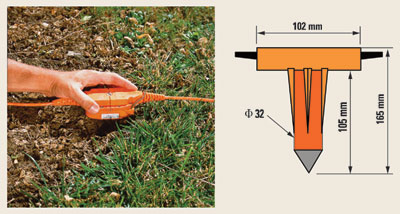 |
Fig. 8. Small and light, weighing just 600 g.
|
|
 |
Fig. 9. Linear response: Low-frequency response of geophone and DSU.
|
|
Due to its high dynamic range, the DSU is able to record extremely low-level signals (e.g., from fluid interface reflections) in the presence of noise from surface sources. However, MEMS-based technology will not universally replace conventional coil-based sensors in every application – especially in very noisy environments, but elsewhere, the benefits are noteworthy.
Input/Output
Fifteen years of R&D resulted in I/O’s VectorSeis MEMS technology. The sensor consists of several stacked silicon wafers. A proof mass is suspended from springs etched out of the silicon wafers. Gold electrodes are deposited on the surfaces of the proof mass, and any movement in the proof mass can be detected by measuring the change in capacitance across these electrodes. A balancing charge is placed on the electrodes to restore the proof mass to its normal position. An ASIC circuit is used to perform this force rebalancing, and a 24-bit digital output is generated directly within the sensor unit.
Since the proof mass is very small, and the rebalancing mechanism is very fast, the sensor is able to respond to signals well beyond conventional seismic bandwidth. The displacement of the proof mass is also tiny. The device operates at all times within the linear region of the silicon springs, making fidelity of the recording very high.
Sensor output is a direct broadband measure of acceleration, from DC to very high frequency. Since the continuous component of acceleration is gravity, this sensor is able to determine the component of gravity within the plane of the sensor. The sensor comes packaged in nodes, with three mutually orthogonal sensors, allowing the node to determine its true vertical orientation with an accuracy of 0.5° or better – an improvement in vector fidelity of up to 20 dB over conventional sensors.
This technology has been commercial and proved successful in many onshore applications over the last two years. Now, it moves into the offshore environment. When used on the seafloor as in OBC systems, by determining its own orientation, the sensor eliminates the need for expensive ROVs to plant sensors, as well as eliminating expensive and unreliable gimbaling systems, without the loss of low-frequency response associated with most omni-directional phones.
The small size and simplicity of these sensors enables the construction of smaller, simpler, more flexible and more rugged seafloor cables, Fig. 10. VectorSeis-based seafloor cables offer enhanced operational efficiency, improvements in cable handling and safety, Fig. 11. 
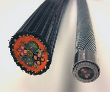 |
Fig 10. Comparison of OBC cables.
|
|
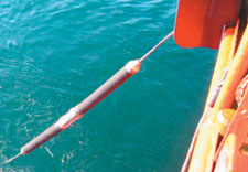 |
Fig. 11. Deploying an OCB sensor.
|
|
|