|
|
|

By Petroleum Technology Transfer Council |
Two-piece, flow-thru plunger offers benefits for unloading gas wells
Production increased and chemical costs were eliminated
Robert Lestz, ChevronTexaco, Houston
ChevronTexaco has successfully employed two-piece, flow-through plungers in South, East and West Texas. By virtually eliminating the shut-in time required for a traditional plunger, lost production is minimized, fewer liquids are forced back into the formation, and less surface fluctuations are encountered. In one well where a capillary string installation was replaced, production increased and $1,740 per month of chemical costs were eliminated. In a 10-well program in West Texas (replacing standard plunger lift in eight wells and two flowing wells), production increased 1,200 Mcfd.
THE PLUNGER
Traditional plunger lift requires shut-in time for the plunger to fall back to bottom and to allow for bottomhole pressure to build. This shut-in time results in lost production and forces liquids back into the formation. The Pacemaker plunger operates as two interdependent pieces – a cylinder and a ball (Fig. 1) – each of which fall separately and are designed to do so against a significant gas flowrate. Once the cylinder reaches bottom, it encounters the ball, which seals off the cavity in the cylinder. Gas is now forced to travel around the cylinder. The gas velocity around the cylinder results in a drag force, causing the cylinder and ball to return to surface, thus acting like a piston. Once on surface, a rod in the lubricator separates the ball from the cylinder, allowing the ball to fall back to the bottom.
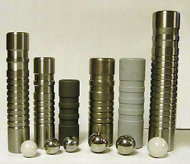 |
Fig. 1. Different sizes and materials of two-piece flow-through plungers.
|
|
Only 5 – 10 sec. of shut-in time per cycle is required. This minimizes production fluctuations and means less interference for wells sharing the same facilities and/or compression. The longer flow period means more production, and liquids are not forced back into the formation. Stabilized production allows liquids to be produced as opposed to accumulating in the near-wellbore area, reducing the relative gas permeability.
APPLICATION ENVIRONMENT
The plunger can be employed in a wide variety of well configurations, including tubing packer completions, open ended tubing, monobore completions (no annulus), and as a replacement for capillary strings and standard plunger lifts. The system has been employed in conjunction with single well compression, and on both sides of a dual completion.
There are some limitations. Since this plunger system is driven by gas velocity, it works best at low wellhead pressures. With 80 – 100 psi of flowing tubing pressure, the plunger system performs best when unloaded gas rates exceed 150 – 200 Mcfd. Very high liquid rates impede the ball’s fall and can result in the cylinder catching the ball prior to reaching bottom. Wellbore restrictions, tubing set too high or excessive sand production will prevent optimum performance. Finally, those involved must understand that the critical factor is gas velocity, not pressure as with a conventional plunger lift system. Training as to how to set the controller, troubleshoot and optimize is critical.
FIELD EXAMPLES
Annotated production rate curves for several field applications illustrate the benefit of the two-piece plunger design. A South Texas well that benefited initially from a capillary string subsequently began producing more condensate and became more difficult and expensive to operate, Fig. 2. The two-piece plunger system was installed in October 2002. Production has increased and become more consistent, producing an incremental 30 – 50 Mcfd. Prior chemical costs of $1,740 per month have now been eliminated. Fig. 3 illustrates a 100 Mcfd production increase when replacing a standard plunger in a West Texas well. A group of ten wells in West Texas showed a total increment of 1,200 Mcfd after conversion to the two-piece, flow-through plunger system, Fig. 4. Eight of these wells were converted from standard plungers and two were previously flowing wells.
 |
Fig. 2. South Texas example: capillary string vs. Pacemaker.
|
|
 |
Fig. 3. West Texas example: standard plunger vs. Pacemaker.
|
|
 |
Fig. 4. West Texas field test: normalized production from all wells.
|
|
ACKNOWLEDGEMENT
The author thanks ChevronTexaco management for allowing this work to be shared. Technical conversations and data contributions from Eddie Bruner, Reed Lawrence, Brent Brugger, Travis Flowers and Beverly Thames of ChevronTexaco are greatly appreciated. Insights and suggestions from Gordon Gates, David Lewis and Preston Abbott of BP are also acknowledged. Editorial suggestions from Lance Cole, PTTC, are acknowledged and appreciated.
THE AUTHOR
|
| |
Robert Lestz is a senior petroleum engineer with ChevronTexaco. He has worked the Mid-Continent, Fort Worth basin, North Texas and South Texas areas as a production/reservoir engineer responsible for new well completions and base-production optimization. In 2001, he served as a technical consultant for ChevronTexaco’s New Ventures Group. Currently, he works for ChevronTexaco’s technology company focusing on hydraulic stimulation, coil tubing, monobore construction, and optimization of low pressure/depleted reservoirs. Robert is a petroleum engineering graduate of The University of Texas at Austin. rsle@chevrontexaco.com.
|
| |
|
|

