Advanced pressure monitoring system reduces costs, improves wellsite control
For over 70 years, the oil and gas industry has been injecting pressurized water underground to enhance recovery and store briny water that is a byproduct of production. However, if the injection pressure gets too high, nearby groundwater is at risk of contamination from hydrocarbons.
To keep the pressure below an amount calculated for each injection site, the EPA regulates underground injection control (UIC) under the auspices of the Safe Drinking Water Act (SDWA), Sections 1421, 1422 and 1425. Oil and gas producers are benefitting from cloud-driven, automated data acquisition and reporting technology that optimizes control over their UIC operations while streamlining compliance with EPA requirements.
Who’s impacted? The EPA estimates that there are about 180,000 wells used in petroleum enhanced recovery and storage applications, mostly in Texas, California, Oklahoma and Kansas. These Class II injection wells, as the EPA labels them, inject more than two billion gallons of fluids into the ground every day. About 80% of the Class II wells inject water for enhanced recovery. This involves the injection of fluids consisting of brine, freshwater, steam, polymers or carbon dioxide into oil-producing formations, to recover residual oil and, in limited applications, natural gas.
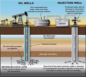
The injected fluids displace the oil or gas, increasing the availability for recovery or thermally expand the oil to make it less viscous. A typical enhanced recovery configuration might involve a single injection well that would introduce water underground, surrounded by multiple production wells that pump the freed oil and gas to the surface.
The remaining 20% of the Class II wells are storage wells. Extraction of oil and gas usually produces substantial amounts of brine, often saltier than seawater. This can damage the environment and public health if discharged directly into water bodies or on land. So, most states have implemented rules preventing brine disposal to surface water bodies and soils, making underground injection the preferred way to dispose of this waste fluid.

Protecting freshwater supply. The EPA requires each Class II well to keep pressure below a specified maximum allowable surface pressure (MASP), determined according to formula on a project-by-project basis. An appropriate MASP helps ensure that injection pressures will not damage confining layers of related underground formations and cause fluid to leave an approved injection zone.
Producers in California, among other states, are responding proactively to the protective regulations by implementing continuous monitoring systems with the ability to control, evaluate, and report process values measured at each of the Class II wells. According to California Code of Regulations Title 14 § 1724.10.4, any Class II well operators that cannot demonstrate effective underground injection pressure monitoring capability, as of April 1, 2021, are subject to fines of $25,000 a day.
Determining MASP. In California, the method to calculate MASP is to multiply the true vertical depth of the shallowest portion of the well open to the injection zone by the difference between the “injection gradient and the injection fluid gradient.” (MASP = (IG–IFG) * TVD).
To build in a reasonable safety factor, the injection gradient should be the product of the fracture gradient multiplied by 0.95. However, an operator could propose a different multiplier on a well-specific basis to account for factors, such as friction loss. Other factors considered in MASP calculations in California are:
- Keep MASP below the fracture pressure, as determined by a step-rate test conducted in the presence of a government official (14 CCR § 1724.10(i).
- Take test pressure from the hydrostatic level to the pressure required to fracture the injection zones or the proposed injection pressure, whichever occurs first. Do not use friction loss to measure MASP, except for safety purposes as an additional margin of error.
- Monitor all injection wells to confirm that injection is at or below the approved MASP on each. If the injection pressure exceeds the approved MASP, the operator must reduce it immediately.
- Perform standard annular pressure tests (SAPTs) for each injection well before beginning operation and repeat at least once every five years thereafter ((14 CCR § 1724.10(j)(1).
- Ensure that all injection piping, valves and facilities meet or exceed design standards for the maximum anticipated injection pressure and are maintained in safe and leak-free conditions (14 CCR § 1724.10(f)).
- Where there is only a single string of casing across water protected by the U.S. Safe Drinking Water Act (SDWA) (10,000 mg/l of total dissolved solids (TDS) or less), test the standard annulus pressure (SAPT) at the approved MASP.
- Compliance fundamentals. Once MASP is established, California compliance requires implementing a system that monitors well-specific pressure operations for pressures exceeding MASP, transmits data for record retention and reporting.
- Implement continuous injection pressure monitoring for as long as the state has approved the well for operation, continuing the monitoring, even when not injecting pressure.
- At the end of each month, report the highest recorded instantaneous injection pressure that each injection well reached in the most recent preceding calendar month.
- Optionally, use digital or analog pressure recording devices to gather and communicate data and send it directly to an information system capable of continuous recording.
Alarm notification is suggested but
not required. - Or instead of the above, demonstrate the configuration of injection facilities to prevent injections from reaching maximum allowable surface injection pressures.
- Maintain injection pressure records for three years after the well is no longer approved to operate.

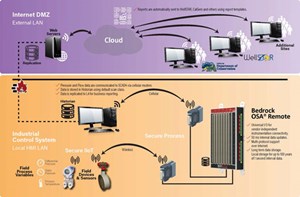
Automating compliance. As operations become more digitized, companies implement automation systems to monitor and transmit data to regulatory agencies. Figure 2 represents the architecture of a turnkey surface pressure monitoring system that would gather pressure data from pressure sensors located at the injection point and compares readings to the MASP. Field devices, such as differential pressure, static pressure and temperature sensors, send pressure information to a controller through hardwired, VPN or wireless sensors. The controller processes pressure logic according to the MASP measurement algorithms and sends it to a web server, which transmits it to the cloud for distribution to regulatory agencies.
In the California system, the data go to the state’s WellSTAR application, which manages data on compliance, incidents, complaints, construction site well reviews, e-permitting, production reporting, underground injection control data, and facility management. It enforces a standard format that automatically populates repeatable data. WellSTAR also has a Well Finder that displays maps and other information about oil and gas wells and their associated facilities throughout California. Users can search by address, oil and gas field names, latitude/longitude, unique well number (also known as “API”) or Public Land Survey System (PLSS) section/township/range. Well Finder is available as a standalone program for public use.
Open secure compliance. Applying this architecture to wells located in remote regions can be challenging and expensive, using a VPN or hardwired connections. Using public carriers, TCP/IP or wireless connections, on the other hand, can reduce costs dramatically, provided they can be secured.
In Fig. 2, the controller providing the processing capability is a Bedrock OSA remote controller, which has built-in encryption and authentication in its electronics. This provides a secure tunnel between the field devices and the receiving applications, which subjects any signals seeking to interact with the controller to the same high-security levels used by major financial, aerospace and defense systems. And because cyber security is intrinsic to the system, it comes at no additional incremental cost.
Another no-cost benefit to the Bedrock OSA remote controller is that it contains 64 GB of data, meaning a single controller can store hundreds of years of pressure monitoring data without an external server required. To reduce implementation and operating costs, any controller used should offer fast data updates, universal I/O, software programmable I/O, multi-protocol support over TCP/IP, long-term and local storage, and be ruggedized to withstand extreme environmental conditions.
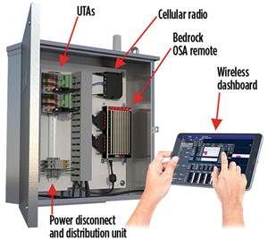
Implementation. Users might interact with a UIC system through their SCADA systems, Fig. 3. Using a wireless dashboard, the operator can get an instantaneous reading of the pressure and see how it changes in relation to the MASP. California law requires reporting on maximum pressure once a month, but any system should alert operators on an anticipated over-pressure event in real time to prevent imposed fines through corrective adjustments.
A UIC pressure monitoring system should receive pressure readings and other production data from multiple pressure sensing devices, process the related control logic, and exchange data with the cloud or SCADA system via MQTT or OPC UA. It should have adequate onboard flash memory to store injection data for many decades.

A typical monitoring solution would have the following basic components: 1) a cellular radio, which carries data signals from the OSA remote to the cloud or SCADA application; 2) universal terminal assemblies, which simplify access and termination; 3) a power disconnect and distribution unit, which manages 24 V dc for safe and easy troubleshooting; and 4) an embedded SCADA dashboard for secure wireless visualization into the process. Such a system would run on a 9-30 v dc power supply, including direct solar arrays, or use standalone components, such as a Bedrock SPS.500 secure primary power supply or a Bedrock UPS.500 cyber secure uninterruptible power supply.
Application design considerations. Implementing pressure monitoring in remote areas presents other challenges, some of which can be met with simple design decisions. Using electrical instead of pneumatic valve control saves the trouble and cost of operating an air compressor at each well, just to supply instrument air for a single valve. A motor-controlled valve with an electronic board converts a 4-20 mA signal into a valve position driven by a low-voltage motor.
Ordering pressure transmitters with advanced diagnostics and then bringing those diagnostics into your PLC could help identify instrument malfunction, such as a plugged pressure sensing line and avoid fines from what might otherwise be interpreted as over-pressure situations. An instrument sensing line could, for example, be plugged by rocks or debris. Some transmitters can detect such plugging. Ordering advanced diagnostic module add-ons to transmitters would enable adding diagnostic information that provides insight into transmitter health and preventative maintenance.
Standalone power can be valuable for remote pressure monitoring applications as well, particularly when the components provide in-line filtering and surge immunity protection. In remote RTU installations, you are often dealing with aging power grids and end-of-life equipment. This results in delivery of dirty power to remote stations. Choosing a secure and filtered power source can help mitigate the damage associated with dirty power by cleaning and filtering the power before powering expensive end components. Accepting dirty power as-is can result in early failure to expensive instrumentation, radios, HMIs, network equipment and cause long-term downtime repair costs.
Basic compliance functionality. A turnkey UIC monitoring and reporting system would handle all data monitoring, analysis, control and reporting necessary for compliance with EPA regulations and include universal communication protocol support, such as OPC UA, and MQTT Sparkplug B. It would simplify and reduce the cost of compliance by accomplishing the following:
- Collecting real-time data from field-based sensors and issue monitoring status via the cloud.
- Securely sharing continuous information to all connected stakeholders.
- Preventing operating fees and overpressure injection sites by safely monitoring and controlling pressure at the wellhead.
- Authenticating users against role-based access to ensure qualified changes to the system.
- Activating fail-safe programming when failure mode conditions arise.
- Implementing controller-based alarm detection and mitigation tools.
- Maintaining decades of secure digital records (California regulation requires a minimum of three years after the well stops operating).
Value delivered. Moreover, producers who can demonstrate that they have adequate automation functionality to keep pressures within the MASP can waive the reporting requirements. They can do this through the Bedrock Automation integrated development environment by programming the control in an instance of the standard proportional-integral-derivative (PID) function block. The PID function block will work as a closed loop controller to automatically adjust control valves to maintain regulated pressures. Securing closed-loop control of pressure injection removes wells from the compliance requirements and contributes to operational excellence while protecting drinking water. It is a true win-win situation.
- Advancing offshore decarbonization through electrification of FPSOs (March 2024)
- Digital transformation/Late-life optimization: Harnessing data-driven strategies for late-life optimization (March 2024)
- The reserves replacement dilemma: Can intelligent digital technologies fill the supply gap? (March 2024)
- Digital tool kit enhances real-time decision-making to improve drilling efficiency and performance (February 2024)
- Digital transformation: Digital twins help to make the invisible, visible in Indonesia’s energy industry (January 2024)
- Digital transformation: A breakthrough year for digitalization in the offshore sector (January 2024)
- Applying ultra-deep LWD resistivity technology successfully in a SAGD operation (May 2019)
- Adoption of wireless intelligent completions advances (May 2019)
- Majors double down as takeaway crunch eases (April 2019)
- What’s new in well logging and formation evaluation (April 2019)
- Qualification of a 20,000-psi subsea BOP: A collaborative approach (February 2019)
- ConocoPhillips’ Greg Leveille sees rapid trajectory of technical advancement continuing (February 2019)


