TCP solves corrosion challenge in Eni’s Aquila deployment
Between 2014 and 2017, an initiative at Rome-based Eni SpA transformed the company into a global supermajor, with a market capitalization of $64 billion. The renovation was accomplished by focusing on innovation, efficiency and HSE improvements. Part of the plan was to update subsea fixtures in Aquila field, found in 1981 in 2,790 ft of water, approximately 73 mi off Brindisi, Italy, in the Strait of Otranto. The strategy at Aquila would be to increase efficiency by extending tool life and lowering maintenance costs. In 2017, Eni approached Magma Global to discuss Aquila field. Their challenge was to find a reliable, easily deployed solution for high sour-gas injection on two wellsites, which would meet their design life requirements. The solution was to provide two 2½-in. gas lift jumpers, 40 m long, that could withstand sour service conditions.
SOUR SERVICE CHALLENGE
Solving the challenges of sour service corrosion, in an easy-to-handle lightweight solution, was the major challenge at Aquila. Flexible hose and non-bonded flexibles have been a common choice for temporary subsea wellhead connections, since they can flex around existing subsea architecture. However, sour service and collapse resistance requirements have led to a significant reduction in the design life of most flexible options. This has required operators to seek a more reliable, long-term solution, such as thermoplastic composite pipe (TCP).
TCP technology. The main benefits of TCP, over rigid steel and flexibles, are its corrosion resistance and strength-to-weight ratio. TCP is typically 1/10th of the weight of an equivalent steel pipe, which enables different and more efficient architectures and installation methods to be utilized, compared with steel and non-bonded flexibles. Fused with Victrex PEEK polymer, the m-pipe carbon fiber pipe resists degradation from oilfield chemicals, including H2S and CO2, Fig. 1; chemicals that are prevalent in many offshore developments and which can degradate steel and flexible pipe. The PEEK-infused TCP has a smooth bore, which minimizes the build-up formed by production fluids, for a higher rate flow. The use of PEEK also gives m-pipe a high-temperature capability and, due to its low permeation, it is ideal for gas application.
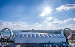
Due to the intrinsic strength of carbon fiber, and the way it is laid and fused together, TCP pipe requires relatively small quantities of material to deliver required pressure performance, which is cost-effective. Significant cost-savings also can be realized during installation, as the pipe is light and will reduce the installation top tensions, making it possible to deploy from smaller, less costly vessels. The pipe also can be manufactured in optimized section lengths, Fig. 2.
REQUIREMENTS
The wellhead connection structures at Aquila-2 and -3 are complex, and have configurations that ruled out rigid and other flexible pipe solutions. Our challenge was to deliver a product flexible enough to accommodate the complex subsea architecture, and still be relatively easy to install, utilizing the Bourbon well-service vessel. The pipe also would have to meet the required design life and be delivered quickly.
Within eight weeks, we had to manufacture the pipe and procure the end-fitting materials, machine, corrosion protect, fit/test, package, and transport to dockside in Italy, to the installation vessel. In parallel, the installation plan for this new technology was developed to ensure that the two spools could be installed efficiently from the Bourbon vessel.
“Eni chose the TCP product, because it performs strongly in sour conditions and has superior collapse resistance capabilities in deepwater applications. The financial case, lead time and ease of installation using m-pipe TCP stacked up well vs. other flexible alternatives,” said Marco Serricchio, Eni production manager.
JUMPER DESIGN
Engineers began by confirming the loading envelope for the pipe structure. The pipe body design process involves analysis of all load cases from installation through service life. It is possible to modify the lay of the tape angle to optimize the wall thickness, but, due to time constraints, it was agreed that the angle would be fixed. Another key design requirement was determining the installation radius that would be needed to accommodate the permanent in-place configuration. This was complex, and it needed particular focus, due to the complexities and congestion around the well flange location on subsea wells Aquila-2 and -3. We provided the client an installation process, which was modeled on Orca Flex. This outline was then incorporated into detailed installation procedures used by Bourbon offshore.
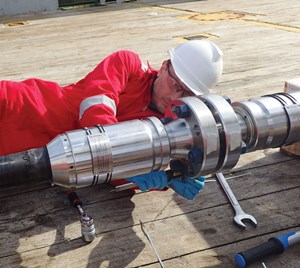
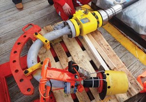
Magma has standardized end termination designs that manage the transfer of loads from the pipe into a steel end termination, and the sealing as two independent solutions that provide a high-integrity solution. The end terminations design philosophy enables m-pipe to interface through a variety of interfaces, from flanges to Greylock or other hub types, pin and box connectors and proprietary connections, as required. For the Eni jumper, the end fitting is designed with an API 6A flange, to properly interface with FMC sub-assemblies, Fig. 3.
Magma has two types of end fitting. The Type-1 is factory-fitted and has an unrestricted bore. The Type-2 is designed to allow for in-field end terminations. For Eni’s application, Magma chose its Type-1 connection. Type-1 end fittings have a build-up on the end of the pipe, using the same automated manufacturing methods and materials as the core pipe. The thickened pipe wall is then machined to a tapered profile and interfaced with a steel collar and interface hub. The end fitting assembly is heavily preloaded to produce an efficient and reliable structural load path. A preloaded PEEK AX type gasket is used between the metallic hub and pipe build-up. In sour service applications, such as the Eni location, the material selection requires special attention. The end fittings used for the Eni jumper were manufactured from Super Duplex, eliminating the requirement for additional coating or weld in-lays and reducing supply time.
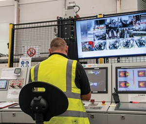
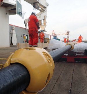
To speed delivery, the 40-m jumpers were manufactured in 20-m lengths, using automatic, robotic, 3D laser printing. This streamlined manufacturing and allowed for faster, more cost-efficient shipping. Both jumpers were supplied with a mid-line flange connection (Fig. 4) and with 20 ballast modules to be clamped to the jumpers, to facilitate on-bottom stability.
DEPLOYMENT
After manufacture and factory acceptance testing of the jumpers at the Portsmouth, UK, facility, Magma engineers travelled to Aquila to oversee delivery and deployment by the installation contractor. The on-site engineers had not directly encountered any type of carbon fiber TCP flexible pipe, as it was a new technology, and did not know what to expect or how to handle the product. They were concerned that the pipe might not be as flexible and compliant as predicted. These concerns were alleviated quickly during execution of the on-deck handling and preparation of the pipe for subsea deployment.
The low weight of the flexible jumper was confirmed during removal of the pipe from the delivery box. The Bourbon engineers had planned to use auxiliary cranes to lift the pipes out of the packing cases, with all the usual precautions for steel and flexible pipe. We recommended a simpler solution and asked for four people to assist with lifting the pipe out of the box by hand.
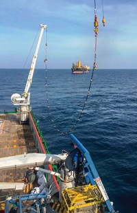
The lift was completed successfully without the need for mechanical equipment, and the two pipes were positioned on deck. The pipe flanges were aligned by hand, and the flange connection was made, resulting in a 40-m pipe section. Each end of this pipe had a steel gooseneck attached with the associated remote stab and hub connection system, Fig. 5. This spool assembly also had small half-shell weights added along its length, to assist on-bottom stability for the as-installed condition. The installation process then used the vessel’s two cranes to pick the pipe up from the vessel deck and lower it into the water, in a simple catenary configuration, Fig. 6. The assembly was lowered to a 40-m water depth, at which point the spool was moved into a vertical position by lowering the main crane.
With all the weight transferred, the main crane was detached, and the spool was lowered in vertical position to 20 m above the seabed. The ROV surveyed the wellhead and PLET conditions, to ensure that the site was ready for spool deployment. Then, the main crane was reattached in heave compensation mode to the free-end of the spool, and the pipe and m-pipe were maneuvered into place at the PLET. The ROV assisted the stab-in and connection; this process was completed faster than expected, without incident. The main crane was released, and the second end was then routed, using the auxiliary crane with some assistance from the ROV; the installation radius required was tight, and the ROV and crane maneuvered the pipe into position at the wellhead end.
Again, the stab-in connection was completed without incident and ahead of expectations. The as-built survey identified that the pipe had performed as predicted, and the pipe was in place without any compromise to the MBR. This process was then completed for the second Aquila well.
VALUE ADDED
The Eni jumpers were installed in under eight weeks, from purchase order to completed deployment. After almost two years, the m-pipe gas line jumpers continue to perform at the Aquila-2 and -3 oil wells and are 10% into their predicted lifespan of 20 to 25 years. “The light weight of m-pipe made the deployment very easy, using our vessel cranes, with trouble-free and fast connection to the two deepwater wells,” said Patrick Belenfant, V.P., Subsea Services, Bourbon. The feedback from Eni and Bourbon has shown that the short timeframe for the installation at Aquila of two flexible gas-line jumpers was successful. It serves as a successful case study for future developments.
Magma has learned that streamlining internal inspections and standardizing pipe designs, coupled with a flexible manufacturing process, enables faster installation design and delivery than steel and other flexible products. The successful Eni project has encouraged a greater level of confidence from other clients, meaning that carbon fiber pipe is being embraced more readily for its ability to perform in sour service conditions, under high pressures and at high temperatures.
FUTURE DEVELOPMENTS
Magma is working on strategic programs that should enable the company to deliver next-gen hybrid flexible pipe for a riser application in Brazil with our partner, TechnipFMC. Engineers are also working on a hybrid riser tower with Ocyan and BrasFELS. For the long term, Magma plans to develop pure TCP riser designs that will deliver simpler, and more lightweight architecture than on other deepwater developments.
- Advancing offshore decarbonization through electrification of FPSOs (March 2024)
- Subsea technology- Corrosion monitoring: From failure to success (February 2024)
- Driving MPD adoption with performance-enhancing technologies (January 2024)
- Digital transformation: A breakthrough year for digitalization in the offshore sector (January 2024)
- Offshore technology: Platform design: Is the next generation of offshore platforms changing offshore energy? (December 2023)
- 2024: A policy crossroads for American offshore energy (December 2023)

