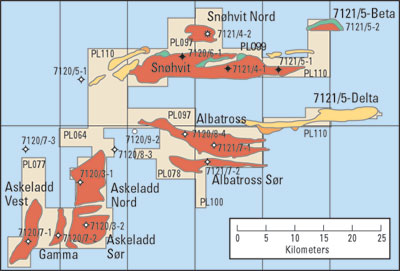
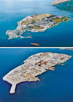
Automation & ControlSubsea-to-beach, long-offset control system employed at SnøhvitA new system for Statoil’s Snøhvit project has overcome difficult technical challenges, representing a significant advance in long-offset control. Several technologies have been combined to provide a significant stepping stone for future subsea-to-beach projects.The Snøhvit field project in the Norwegian North Sea is a milestone in offshore oil and gas development. It will be the first Norwegian and European production and export facility for LNG. Snøhvit is 140 km (88 mi) from the northern Norwegian coast, and its production will be piped to a receiving and liquefaction plant on Melkøya Island, outside Hammerfest, Fig. 1. This field is the first development in the environmentally sensitive Barents Sea. It is located at 71° 30’ north, within the Arctic Circle and 1,000 km (620 mi) north of Norne field, currently the most northerly producing field offshore Norway.
After processing and liquefaction, LNG will be shipped in special carrier vessels to Spain and the USA. Approximately 70 consignments are due to be exported annually over the field’s life of almost 30 years. Snøhvit is Norway’s first offshore development with no surface-piercing installations. The pipeline carrying output from the subsea installations to Melkøya is 145 km (90 mi) long, a world record distance for piping an unprocessed wellstream. The associated subsea control system will also be a world record for long-distance tie-back. The ultimate field development (Fig. 2), which includes the reserves of Askeladd, has resulted in a control system that has a total offset capability of 220 km (136 mi).
It has taken some time for the technology to evolve, to enable Snøhvit’s development. The primary technology gaps that had to be closed were the long offset control and a compact, efficient LNG plant, together with long-offset multiphase flow. In combination, these technologies allow subsea development without the need for a conventional surface structure.
The first gas discovery was made in 1981, and the blocks containing the three discoveries were awarded in 1984 and 1985. So far, 16 exploration wells have been drilled in the area. In May 2002, Statoil obtained approval from the Norwegian government to develop Snøhvit. By June 12, 2002, construction work had begun on Melkøya, with first production scheduled for 2006, Fig. 3. The subsea development envisages about 21 production wells and a carbon dioxide disposal well. This disposal well represents a large portion of the development’s much-reduced environmental impact (700,000 t of CO2 from the reservoir is reinjected each year). The focus on environmental impact is, of course, due to the area’s environmentally sensitive nature and the fact that it is an important fisheries area. Clearly, the use of a subsea development remotely controlled from shore is a cost-effective solution that contributes to ensuring safe shipping routes and is in line with Norwegian practice. The subsea templates are designed so that trawlers pass over easily, and the pipeline routes are also chosen to reduce their possible hindrance to fisheries. Recoverable reserves are estimated at 190 Bcm of LNG, 113 million bbl of condensate and 5.1 million t of LPG. The field concept is sized for a wellstream output of 20,800 m3/d (130,830 bopd). The project has positive socio-economic benefits for the economy of the local Finmark area. When production gets into full swing in 2006, the gas produced will represent a large contribution to Norway’s total gas exports. FIELD DEVELOPMENT Development of the Snøhvit reservoirs is based on horizontal trees with recoverable choke bridge modules mounted on four-slot templates. These templates are located at appropriate points on the seabed above the reservoirs. Connections between the “tree/ choke bridge” systems and the infield flowline are via a manifold on the template. For the Phase 1 Snøhvit and Albatross development, there are four templates designated “D,” “E,” “F” and “N.” While “D,” “E” and “N” are gas production templates, template “F” is a dual-header gas production and CO2 injection template, with a single slot dedicated to CO2 injection. For Phase 1, only three slots on each of the “D,” “E” and “N” templates will be utilized, while only the CO2 injection slot will be used on the “F” template. For future phases, three additional templates will be installed at the Askeladd reservoir, designated “J,” “K” and “L.” In addition, further wells will be installed in the existing “D,” “E,” “F” and “N” templates. SUBSEA CONTROL SYSTEM The control system provided by Vetco Gray for Snøhvit field uses a hybrid electrical and optical communications system. It also has electrical and hydraulic power to control the subsea facilities via a main umbilical connected between shore-based control equipment and the subsea system. The Snøhvit hydraulic system is a dual, redundant LP system. All HP supplies are generated at the subsea control module (SCM) by means of high-pressure intensifier units located within each SCM. The hydraulic system is an open-loop vent-to-sea type and uses an environmentally friendly control fluid. The main umbilical terminates subsea at a central distribution unit (CDU), from which power and communications are further distributed to templates via infield umbilicals, Fig. 4.
The control system’s main challenge is the length of the main umbilical between onshore control system equipment and the CDU. This has necessitated use of optical fiber communications techniques to achieve the desired control and monitoring response, and update rates. In the event of the umbilical optical system’s failure, a back-up communications and power system is available, operating via the umbilical power conductors at a reduced communications rate. Should a total umbilical failure be experienced, a back-up intervention control system is provided. This system will replace the main umbilical by providing optical, electrical and hydraulic services from a vessel situated directly above the CDU. The system will be connected, via a dynamic umbilical, with satellite communications links to the onshore control facility. The project requires significant subsea instrumentation, including conventional christmas tree instrumentation and other instruments placed on the choke-bridge module: Christmas tree instrumentation includes:
Choke bridge module instrumentation includes:
In addition, there are pipeline corrosion monitoring devices located 1 km (0.6 mi) and 17 km (10 mi) from the upstream end of the flowline. A third unit is installed in the onshore section of the flowline. The water depth is a relatively modest 350 m (1,148 ft), but the 30-year design life is slightly longer than the average for the subsea controls industry. The challenges of long-range, electrical power supply are many. Issues need to be addressed, such as minimizing the copper content of the umbilical, and the need to produce a subsea transformer that is sized for convenient packaging in standard, retrievable subsea modules. The solution adopted for Snøhvit is a 3-phase, 3-kV link, with a subsea, step-down transformer at the CDU, Fig. 5. Single-phase power is distributed to the SCMs at 600 V.
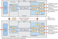
Overall architecture of the control system is dual-duplex and redundant, Fig. 6. For each channel, the bi-directional, full-duplex fibers and modems are, themselves, replicated. They are backed up with low-speed communications superimposed on the 3-phase power supply. The whole system is duplicated by a second channel. The so-called BUICS (Back-Up Intervention Control System) has the option to intervene from a vessel-of-opportunity and connect directly into the power and communications distribution module (PCDM) on the CDU.
Each redundant PCDM contains two optical modems that receive data from a dedicated fiber, Fig. 7. The modems demodulate the fiber optic data and pass them in electrical format to a communications router, where the data are buffered and presented to the high-speed copper modems for onward transmission to the template.
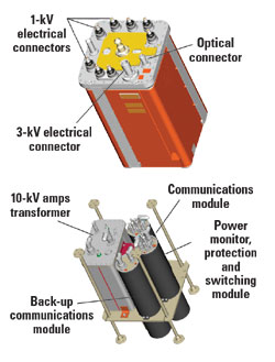
Packaging of the new technology in the PCDM is surprisingly conventional. The module is externally identical to the main SCM for the tree, and it uses the same running tool to retrieve and re-install, if necessary. The PCDM contains the 10-kVA transformer for voltage step-down and communication modules enclosed in conventional pressure-isolating vessels, together with another module for power monitoring, protection and switching. All connections between the subsea system and the onshore components of the control system are via a single, continuous, main umbilical with no intermediate connections or booster stations. The main umbilical contains two separate conduits, each containing 12 fibers, one as channel A, the other allocated to channel B. Within each channel, four fibers are allocated to Snøhvit/ Albatross, four to Askeladd, and four are provided as spares. Of the four allocated to each field, only two are used, dedicated to the two modems in each PCDM. The unused fibers are, however, taken through the distribution system to the connectors in the PCDM and could, therefore, be used at a later stage by suitably re-configuring the PCDMs. The communications system provides a high throughput capability. Each optical modem has a line bit rate of 20 megabits/sec (usable rate is 10 megabits/sec). Data routers, both onshore and subsea in the PCDMs, enable up to eight virtual channels to be multiplexed onto the optical communications links. Subsea, three of these channels are routed to three high-speed copper modems (HSCMs), each dedicated to communicating via one of the electrical power phases. The HSCMs communicate via the infield umbilicals with the tree- mounted SCMs. The HSCMs communicate via the power lines using a spread-spectrum modulation technique. The technology ensures a bit rate on the power line of 268 kbits/sec. This rate is reduced to a usable data rate of 115 kbits/sec, once the adaptive equalization and forward error correction algorithms have been accommodated. The technology and modulation schemes ensure a bit error rate of better than 1 in 10 billion. Communications are maintained with signals attenuated by as much as 90 dB. One other feature of this modem is that because its operating bandwidth is outside other subsea communications systems, it can be operated “on top” of (superimposed on) existing subsea systems to enhance data transmission capability. GAPS, DEVELOPMENT AND QUALIFICATION From a controls perspective, the most significant aspect of Snøhvit is the provision of high control availability over an extremely long distance. As has already been described, long-range communication without repeaters and relatively high data requirements dictated that a fiber-optic link be used as the principal communication means from the subsea location to shore. The long range also led to adoption of a high-voltage, three-phase power transmission system operating at 3 kV. It is clearly important that the necessary technology for implementing the controls solution is fully qualified and reliable. Some years ago, Statoil embarked on a review of available technology, identified a number of gaps and undertook to encourage and fund the equipment suppliers to develop and prove the necessary technologies. In relation to the control system, this included equipment to encompass the following:
SUBSEA PROJECT STATUS The development and qualification of communication modules is complete, with the control system’s extended FAT being undertaken. Subsea structures were successfully installed on July 2, 2004. The installation contractor, Aker Marine, completed installation of four templates (approximately 260 metric tons, each), a 430-metric ton pipeline end module (PLEM) and a 270-metric ton CDU, all within a single calendar month. Three of the templates were installed on the Snøhvit reservoir, with the fourth being installed on Albatross. Following installation of the flowlines between the templates and the PLEM, the subsea umbilicals and main pipeline to shore will be installed during 2005. Production start-up is planned for Oct. 1, 2005. CONCLUSIONS The Vetco Gray control system design for the Snøhvit project has addressed and overcome some difficult technical challenges, representing a significant advance for long offset control. A number of technologies have been combined to provide the necessary, safe and reliable, long-offset control system. Fiber-optic communications modems have been developed, together with a three-phase, 3-kV power delivery system with back-up communication superimposed on the power lines. In addition, as we have noted, a local high-speed, communication-on-power system is used to provide communication and power to the subsea wells. A router implements the communication switching and prioritization. These technologies provide a significant stepping-stone for other subsea-to-beach projects in the future.
|
|||||||||||||||||||||||||||||

- Advancing offshore decarbonization through electrification of FPSOs (March 2024)
- Subsea technology- Corrosion monitoring: From failure to success (February 2024)
- Driving MPD adoption with performance-enhancing technologies (January 2024)
- Digital transformation: A breakthrough year for digitalization in the offshore sector (January 2024)
- Offshore technology: Platform design: Is the next generation of offshore platforms changing offshore energy? (December 2023)
- 2024: A policy crossroads for American offshore energy (December 2023)

