Renewable energy technology: Transforming wind farm anchoring with oilfield technology
Subsea Drive Corporation is adapting oilfield drilling technology, to transition from the global dependence on hydrocarbons for energy to renewable, sustainable, offshore wind electrical energy generation. Many of the practices and technology used in the offshore oil industry can be adapted to facilitate a timely and economically feasible energy transition.
Subsea Drive Corporation’s contribution is transforming riserless casing drilling technology into a subsea anchoring system. The high axial and lateral load capacities are much greater than existing anchoring technology, reducing the number of anchors required from nine or ten to three or four, for a 15-KW turbine per floating structure. This drilling technology can improve the economics of offshore electricity generation, due to its less costly anchoring system with high axial capacities, resulting in less-costly wind turbine platforms. This decreases the cost of offshore wind electricity by minimizing capital costs while decreasing the marine environmental impact with fewer anchors.
TRANSITION FROM HYDROCARBONS TO RENEWABLE GENERATED ELECTRICITY
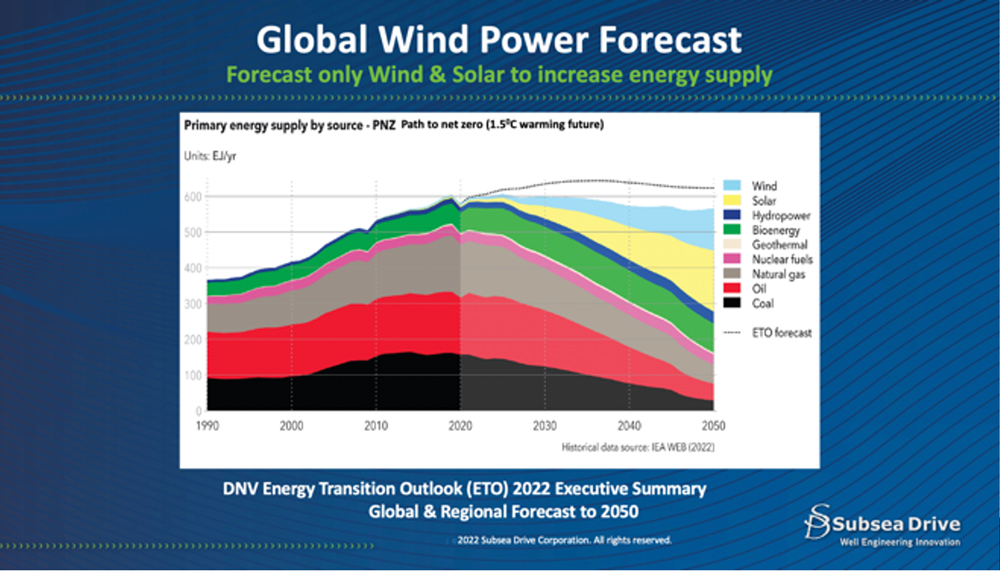
The demand for energy, specifically in the form of electricity, continue to increase. This demand must be met with decreasing dependence upon hydrocarbons. There are numerous forecasts for the global demand for offshore wind-generated electricity. One such forecast, by DNV Energy Transition Outlook (ETO) 2022 for Global and Regional Forecast, indicates that global electricity demand will grow at 3% per year, with half of this demand for road transportation.
A part of the global initiative for energy source transition is that global fossil fuel supply of energy demand will decrease from 80% to 50%. In 2020, oil consumption was about 75 MMbpd; it is expected to peak at 86 MMbpd, then reduce to 56 MMbpd by 2050. The difference in this demand will be supplied partly by wind-generated electricity, expected to rise from current levels of 1.6 Peta GWh per year to 19 Peta GWh per year by 2050. Refer to Fig. 1 for the forecast from the ETO report, indicating the global forecast for various energy sources.
The challenge for the wind generation industry is to reduce the cost of offshore wind-generated electricity to current levels of economic cost for hydrocarbons or other sources of electrical generation. These anticipated cost reductions will come from increased wind turbine capacities to the range of 15 KW or greater, reducing the number of turbines required, and from decreasing the cost of turbine support structures and anchoring systems, amongst other cost reduction initiatives.
THE FUTURE OF ANCHORING TO SUPPORT OFFSHORE WIND ELECTRICITY
An offshore wind-generated electricity forecast, “The Floating Wind Forecast: Mostly Sunny with a Chance of Showers” (Oct 12, 2022, COWI Holdings A/S), indicates the demand for global offshore wind electricity will be 48 GW by 2030. This indicates a very large market demand potential for offshore anchoring systems. This translates to a global anchoring requirement of between 9,000 and 12,800 anchors for wind turbines generating at least 15 KW, using three to four Subsea Anchoring Systems for each turbine.
Existing anchoring technology typically requires nine to ten anchors for such turbine installations, which would be a larger capital cost, compared to the less-expensive Subsea Anchoring System. The Subsea Anchoring System significantly reduces the total cost of mooring and overall capital costs. Cost reductions are required to lower the forecasted, high, per-unit costs of offshore electricity.
MARINE ANCHORING SYSTEMS
The available anchoring systems illustrated in Fig. 2 are selected by specific applications, such as suitability for subsea soil conditions, required anchoring or holding capacity, ease of installation, and cost. They have been developed from marine construction activities except for the Subsea Anchoring System. The anchoring or holding capacities of these methods result from the nature of their contact or the amount of surface area contact they have with the formations below the seafloor. These anchoring systems fall into three categories.
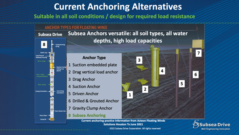
The first category is traditional drag anchors, which depend upon the ability to attach or cling to the seafloor, requiring expensive and elaborate chain mooring systems and occasional re-positioning. Due to their limited anchoring capacities, they have limited applications for permanent floating facilities.
The second category is hammer and suction anchors. Both have unpredictable and limited penetration depths, due to seafloor soil conditions, which limit their anchoring or holding capacities. Not all soil conditions are suitable, such as “hard rock” seafloors or instances where the strength of the formations limits the anchors’ penetration depths. Large-diameter piles compensate for the shallow penetration depths to provide the required holding capacities. These casings are expensive and require purpose-built mobilization, transport and installation equipment.
The third category is drilled and grouted anchor piles, which have limitations, based on formation strengths and stability. Suitable formations must maintain stable hole conditions long enough to run the pile or casing after the hole is drilled. The pile is then grouted with cement, which is problematic for obtaining cement coverage of the entire annulus between the hole and pile. This results in poor circumferential cement contact of the soil to the pile, limiting the axial holding capacity.
THE SUBSEA ANCHORING SYSTEM
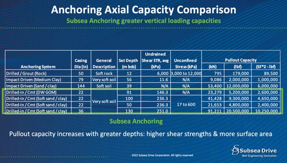
The Subsea Anchor can be drilled to the required depth, using oilfield casing diameters to obtain the required anchor holding capacity. The method of casing drilling allows drilling in any type of formation: soft, unstable, hard, or very hard. Once the casing is drilled to the required depth, oilfield style cementing—as opposed to grouting—is performed, providing optimum casing to cement to formation contact. A comparison of the holding pull-out capacities of various anchoring systems to the Subsea Anchor System is indicated in Fig. 3. The Subsea Anchoring System, with deeper penetration, more contact surface area, and improved cementing, has axial pull-out capacities significantly larger than currently available anchoring systems.
The Subsea Anchoring System utilizes the casing drilling one-trip concept to cement immediately, once anchor depth is reached. Casing drilling is tried and proven oilfield technology. The anchor depth and casing diameter are determined for the project axial and lateral holding capacities. The anchor pile casing grade, wall thickness and length are specified for the required lateral or bending moments. Subsea Anchoring System can set anchors in any water depth or soil/formation condition, using purposed, oilfield-designed offshore drilling vessels.
SCIENCE OF ANCHORING
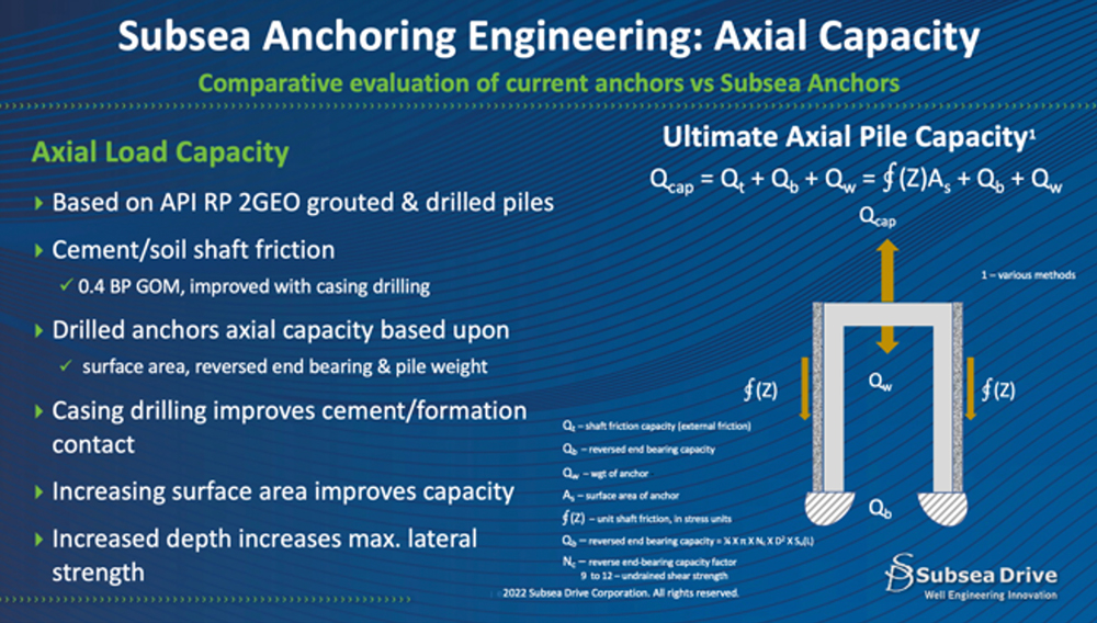
Pile or casing anchoring axial hold capacities are based upon three factors:
- Exterior shaft resistance and/or the internal shaft resistance, dependent upon soil drainage conditions
- Weight of the anchor
- Tension force at base level or end of the anchor.
The largest effect on axial holding capacity is shaft resistance. This is a direct function of the anchor surface area and formation-generated friction. Casing drilling can be done to the required depth for the design anchoring loads. Figure 4 summarizes the physics involved in the axial holding capacity.
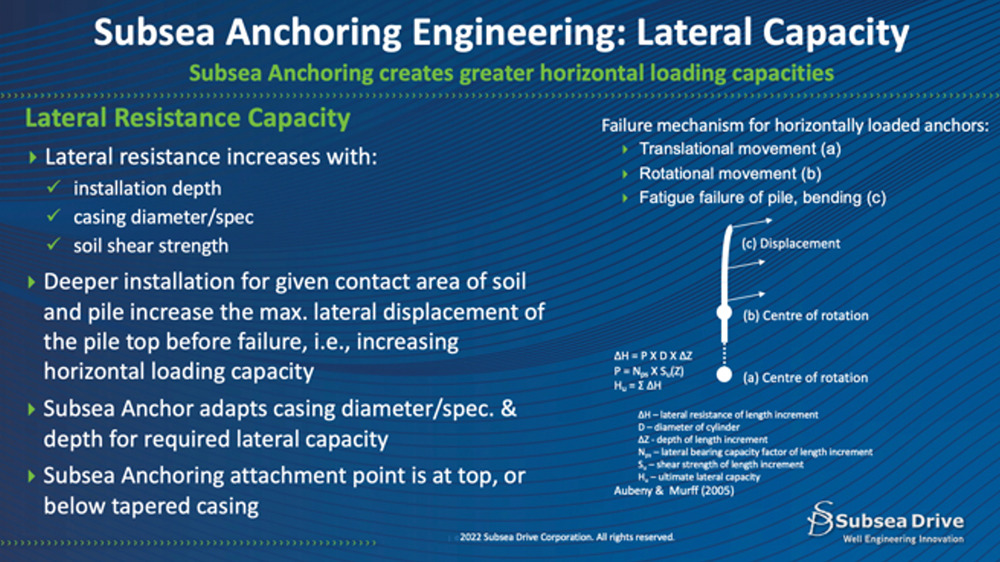
The horizontal lateral capacities of suction anchors are mainly determined by anchor geometry, the position of anchor connecting point, and soil conditions. The lateral failure mechanism will consist of a conical soil wedge nearer the seafloor, with lower strength soil and a flow-around zone below. Placing the load attachment point at the optimum position is critical in conventional anchoring piles, to distribute the loading over the entire anchor. Suppose the attachment point is above the optimum position, such as at the top of the anchor. In that case, the center of anchor rotation will be located below the conical soil wedge within the anchor.
Subsea Anchoring allows the anchor depth, as required, to maintain the center of rotation below the soil wedge, to increase lateral holding capacity. The anchor specifications of wall thickness and grade are chosen for the anticipated bending moment from the anticipated lateral loading. Refer to Fig. 5 for the physics of lateral holding capacity.
RISERLESS CASING DRILLING
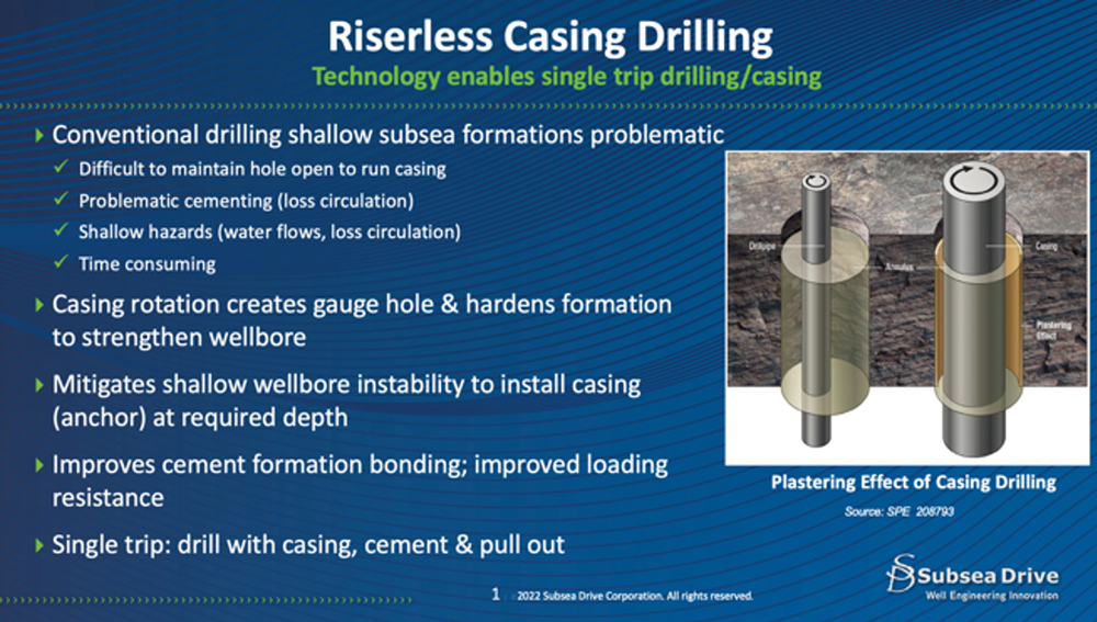
The Subsea Anchoring System is installed with casing drilling. Drilling to the required anchor depth with conventional drilling, then running casing, is often impossible in many offshore soil conditions, due to unstable soil conditions. Furthermore, conventional cementing can be problematic in these soft, unstable formations, causing loss of circulation, while casing drilling strengthens the formation, improving cement displacement.
Casing drilling is a reliable technology for anchor installation, providing many advantages, such as improved cementing, drilling hazard mitigation and the anchor depths required for holding axial capacities. Refer to Fig. 6 for casing drilling summary and advantages.
Casing drilling involves using the casing as the drilling string, with a drill bit installed on the lower end of the casing. The casing material strength is chosen for the required holding capacities and bending moment. The required number of casing joints are connected to be hung from the rotary table of the drilling vessel. Then the Subsea Drive Tool, with an inner string latched into the Subsea Drive sleeve, is lowered to the seafloor with running/drilling string. Rotation of the casing with the drilling vessel’s top drive begins, to start the drilling.
As casing drilling occurs, the drilling fluid is circulated through the drilling/running sting and inner string, returning with drill cuttings that are circulated to the seafloor. The rotation of the casing crushes and smears the returning drill cuttings against the wellbore, to harden and strengthen the surrounding rock or soil.
Specially designed casing couplings have the mechanical strength and the fatigue resistance of casing drilling. Furthermore, engineering evaluation has indicated that the coupling/casing cumulative fatigue damage would be less than 0.03% of the wall thickness and negligible for the connector. There are neither any Von Mises Equivalent stress (VME) over yield strength nor vortex-induced vibrations (VIV).
SUBSEA ANCHORING SYSTEM ADVANTAGES
The Subsea Anchoring System is installed, using existing floating drilling vessels. The installation costs of a Subsea Anchor are less than those of currently available anchoring system, due to the following:
- A drilling vessel is purposely equipped with minimal equipment, not requiring BOPs, riser equipment or a vast amount of normally required drilling equipment for oil well drilling, minimizing the drilling vessel costs. There is no requirement for a purpose-built marine vessel.
- Casing drilling efficiency, with its one-trip system, allows rapid drilling/installation and cementing in less than one day; similar timing to currently available anchors.
- The amount of steel required is significantly less, due to developing the axial load capacities deeper than current anchoring systems with smaller casing diameters.
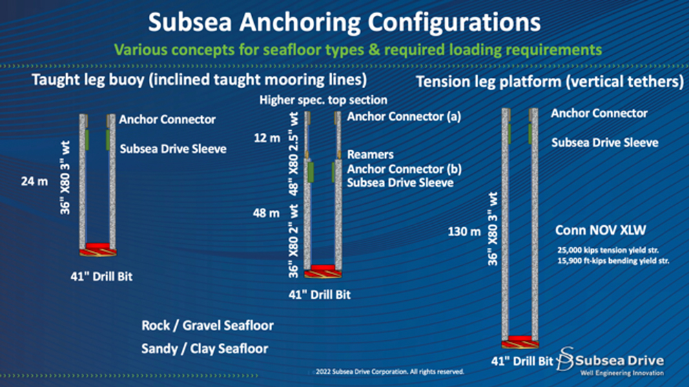
Figure 7 indicates possible Subsea Anchoring configurations, from the shallower, taut leg, inclined mooring systems, to the deeper, installed, vertical tether anchoring. The deeper set anchor results in significantly larger holding/pull-out capacities. The overwhelming advantage of Subsea Anchoring System is providing very high anchoring capacities. This advantage is of value for anchoring spar-type floating structures, which have lower capital costs than those of barge or semi-submersible floating platforms.
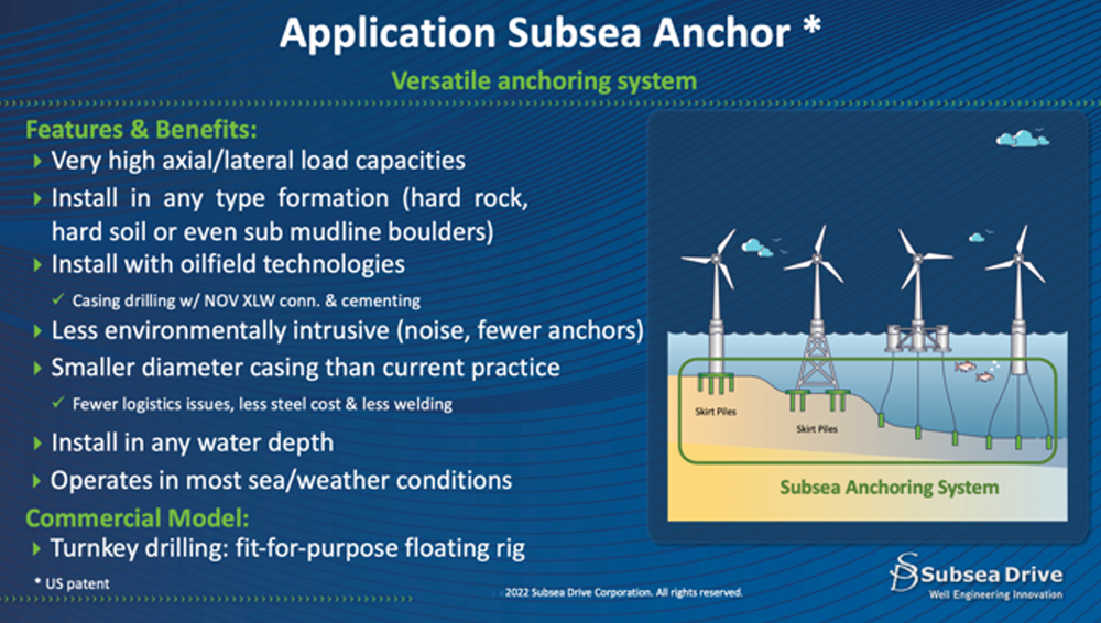
As illustrated in Fig. 8, the Subsea Anchoring System is the most versatile of all offshore anchoring applications. This anchoring system has the major advantage over current practices of providing significantly larger holding capacities than any anchoring system, including either suction installed or hydraulic hammered piles. This Subsea Anchoring System has the following advantages:
- It can be installed in any subsea soil condition, including sub-marine boulders.
- It can be installed in adverse weather and sea conditions.
- It has high axial and lateral loading capacities allowing:
- the reduction of the number of anchors for each floating structure, and
- smaller, less-expensive floating wind turbine structures
- It minimizes environmental marine impact, due to low noise generation and less-intrusive mooring/tension cables or tendons.
- It can be installed in any water depth.
- Its cost is generally less than currently available anchoring systems with smaller oilfield size piles and has more cost-effective logistics.

