Exploring annular phase separation phenomena to optimize AICD completion design, to control unwanted effluents
Advanced completion technologies address the challenges of fluid flow in advanced architecture wells without the need for intervention. They are designed to encourage proportional production or injection of fluids along the length of the wellbore, to delay or prevent the breakthrough of unwanted effluents, and to respond to changing conditions throughout the life of the well.
Autonomous inflow control devices (AICDs), in which the differential pressure of the device is dependent on the composition, density, viscosity or flowrate of the fluid flowing through it, have become popular in horizontal wells. They reduce the production of unwanted effluents, such as gas and water, allowing operators to optimize oil production rates and maximize oil reserves recovered.

A key challenge when designing an AICD completion is establishing the performance rating and number of AICD devices to be used to deliver the target production rates. This is required because of the different flow performance (differential pressure, dP, versus flowrate) for oil compared to water.
Global production optimization specialist, Tendeka, has developed the FloSure AICD, which has so far been installed in more than 600 wells worldwide. This creates a variable, rate- and fluid-dependent pressure drop, based on the gap created between a free-moving disk and the top plate of the housing in which it is contained.2 Flow enters the device through the nozzle in the top plate of the body, impacts the disk and spreads radially through the gap between the disk and the top plate. It then turns around the top plate and is discharged through several outlet ports in the body, Fig. 1.
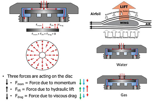
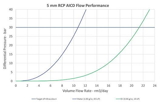
The overall geometry of the device is critical to its ability to balance these forces effectively and create the desired fluid dependent pressure drop. Figure 2 shows the flow performance of one size of the device for single-phase flow of oil (10 cP) and water (0.5 cP) at downhole conditions for reservoir fluids. For any flowrate, the differential pressure across the device is much greater for water than for oil, as shown in the graph.
TWO-PHASE LIQUID EQUILIBRIUM FLOWRATE
The concept of an AICD that completely shuts-off gas and/or water production sounds appealing to those wishing to eliminate the production of unwanted effluents. Yet, a full understanding of the dynamics of inflow from the reservoir and phase segregation in the wellbore is necessary to evaluate the impact of highly restrictive AICDs on well oil productivity.
With annular separation, even small water cuts or limited amounts of free gas flowing into the wellbore can cause most of the highly restrictive AICDs in a multiple device zone to shut. This greatly impacts the oil productivity of the zone and the well. This closure may result in the diversion of fluids inside the reservoir to other zones. On the other hand, using AICDs that are not as restrictive of the unwanted effluents allows the operator to continue to produce oil at significant rates when associated with low water cuts or reduced free-gas GORs.
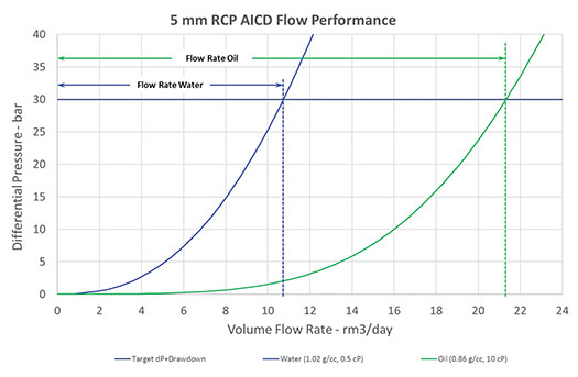
As an example, Figure 3 compares the flowrate of water to the flowrate of oil through a 5-mm RCP AICD at a differential pressure of 30 bar, at downhole conditions. At this differential pressure, 10.7 rm3/d of water will flow through the AICD, while 21.3 rm3/d of oil will flow through the AICD. This type of analysis would project that water flowrates through the AICD would be 49% less than oil flowrates at the same differential pressure.
Unfortunately, this type of analysis does not properly represent what is happening downhole, in the wellbore, nor does it consider the crucial roles of reservoir inflow performance, fluid-phase mobility, and the synergy of reservoir inflow and AICD flow performance. A different type of analysis is required to understand the interaction between reservoir inflow and AICD flow performance.
In a typical horizontal well, placed in a reservoir with uniform reservoir pressure (reservoir not compartmentalized), inflow is created by reducing the pressure in the wellbore to a value less than the reservoir pressure. This establishes a pressure gradient that causes fluids to flow from the reservoir to the wellbore.
Based on the Darcy inflow equation for liquid flow, if the viscosity of oil is significantly greater than the viscosity of water, for a constant pressure drop from the reservoir to the wellbore (drawdown), the single-phase flow of water will be greater than the single-phase flow of oil. If the difference in viscosity is large, for instance, if water has a viscosity of 0.5P and oil has a viscosity of 10cP at downhole conditions, the water flowrate will be 20 times greater than the oil flowrate at the same drawdown (assuming relative permeability is equivalent) flowing from the same reservoir. If water breaks through from the reservoir to the wellbore, the oil production can quickly be overwhelmed by the water production. Water breakthrough in only 5% of the wellbore can result in equivalent water flow as the oil production from the remaining 95% of the oil-saturated wellbore.
To counter this effect, a liner lined with AICDs is installed with swell packers to segment the wellbore into multiple compartments or zones. When water breaks through in one zone, the AICDs in that zone create a greater pressure drop associated with the water flow, and this reduces the drawdown on the reservoir and water flowrate in that zone.
The total pressure drop from the reservoir to the inside of the liner is the sum of the drawdown on the reservoir and the pressure drop through the AICD. Over the length of the well, the pressure in the liner is constant (ignoring flowing friction pressure), and with constant reservoir pressure, different zones will have different balance points between drawdown and pressure drop through the AICDs. This depends on the water cut from the zone and the productivity of the zone.
This information can be used to determine how the balance between drawdown and pressure drop through the AICD is affected by single-phase oil and water flow. It can be used to establish an equilibrium flowrate for each AICD. This value is independent of the permeability of the zone.
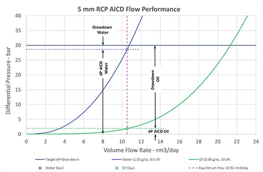
As shown in Fig. 4, this equilibrium point occurs at 10.52 m3/d for the 5-mm RCP AICD with the liquid properties as shown and a total pressure differential between the reservoir and the inside of the AICD liner of 30 bar.
The equilibrium flowrate can be used to determine the number of devices needed in a well with a wellbore inflow simulator. The total well inflow rate without the AICD completion is calculated, assuming the reservoir is saturated with all oil or water (single-phase flow), by imposing the respective drawdown pressure as calculated for the equilibrium flowrate, associated with either phase.
In the example shown, the drawdown for water should be 1.41 bar while the drawdown for oil should be 28.13 bar. The flowrate of the well (in downhole conditions – reservoir m3/d) for either oil or water is then divided by the equilibrium rate to determine the number of devices required. The resulting number of devices, whether calculated based on 100% water or 100% oil, should be similar.
It is widely believed that the ideal Autonomous ICD would be one that would completely shut off the flow of unwanted effluents, or at the very least, provide a very high-pressure drop at a low flowrate. This restricts the flow of water to less than 5% of that of oil for the same differential pressure, known as highly restrictive AICDs.
The moderately restrictive AICD never completely shuts off the flow of unwanted effluents—it only restricts them. This is important to avoid premature shut-off of flow from a zone that experiences a small fraction of unwanted effluent in the zone, or a slug of unwanted effluent that may cause a highly restrictive AICD to close when a significant potential for oil production still exists in that zone. The moderately restrictive AICD will continue to produce fluid from that zone at a more restrictive rate while allowing associated oil to be produced, or allowing the slug of unwanted effluent to pass, so that the surrounding oil can continue to be produced.
Understanding this concept helps the petroleum engineer to understand the performance of a well equipped with an AICD completion, and how the well will perform as fluid composition changes.
MULTI-PHASE FLOW IN HORIZONTAL WELLBORES
Productive wells will often require multiple AICDs in each zone to ensure delivery of desired oil rates with minimum additional pressure drop while being able to restrict zones with water breakthrough. It is important not to be overly restrictive of production in zones with minimal degrees of water breakthrough, say 35% water cut or less, because of the potential to continue to deliver significant oil reserves from these zones. Understanding how the AICDs will behave is key to the correct selection of the type of AICD.
Multi-phase flow of fluid in horizontal pipelines has been studied extensively, and several modes of flow have been identified. In particular, the multi-phase gas-liquid flow has been characterized, and prediction of the mode of flow has been mapped, dependent on several derived measures, including Froude number, volumetric flux and mass flux. The likelihood of phase separation depends on the density, viscosity, surface tension and velocity of the fluids, and residence time in the annular space.
For oil-water multi-phase systems, it can be useful to look at a representative example to understand the conditions for phase separation in the annular space. For instance, a 1,000-m horizontal section with 10 equal zones, each measuring 100 m in length, where the AICD liner is 4.5-in. OD inside the 7-in. casing with an ID of 6 in. The annular cross-sectional area of this completion is 0.00798 m2, and the annular volume of a single zone is 0.798 m3. If we assume that the well can produce 1,600 rm3/d (downhole conditions), then each zone will produce 160 rm3/d or 1.852 liters/sec. That means that the worst-case velocity (all flow moving to one end of the zone) in the annulus will be 0.232 m/sec, and residence time will be 7.18 min.
In reality, the inflow to the annulus is distributed along the length of the zone, and the AICDs are also distributed along the length of the zone. Therefore, it is likely that the maximum velocity is less than 25 mm/sec (residence time remains the same), so it can be appreciated that there are adequate conditions for oil/water phase separation.
Each application will have its unique results, based on fluid properties, well/reservoir productivity, and production expectations. The results will be different for each application, but the modelling techniques used in this exercise can be employed to find the best AICD completion design for the application operating constraints.
SUMMARY AND CONCLUSIONS
AICDs are the next generation of inflow control technology that not only provides a more uniform inflow profile and enhanced production, but also does this autonomously. Tendeka’s FloSure AICD is a proven solution for increasing oil production over the life of the field and has been deployed successfully in light and heavy oil wells to overcome water or gas breakthrough and ensure uniform production longevity.
The device preferentially chokes unwanted produced fluids while promoting the production of oil from the entire length of the well. The device is fully interchangeable, field-adjustable and engineered for a wide range of applications. Deployed as part of the lower completion, using zonal isolation packers to divide the reservoir into compartments, the AICD can be integrated with sand control screens for soft formations.
When considering the application of AICD completions, there are five fundamental rules to remember:
- AICDs react to the properties of the fluids passing through them; there must be a significant difference in viscosity, density and/or other properties.
- AICDs are not downhole separators—what comes into the wellbore must go out via the production conduit.
- AICDs cannot change water to oil:
- To improve oil production, there must be a variation in the oil saturation or oil cut along the length of the wellbore
- High water cut zones will see higher pressure drop across the AICD and thus lower drawdown and lower production rate
- Low water cut zones will see lower pressure drop across the AICD and thus higher drawdown and higher production rate
- If the water cut along the whole length of the wellbore is uniform, the AICD cannot improve water cut
- Moderately restrictive AICDs never fully shut off flow from a zone—this is important to avoid premature shut-off of significant oil production.
- AICDs can be an insurance policy against reservoir uncertainty and allow maximum drawdown on zones with low water cut.
Most notably, the concept of the equilibrium flowrate for an AICD completion is useful, not only as a tool to help establish the number of AICDs required for a completion, but also to understand the relationship between inflow from the reservoir and flow through the AICDs.
While the calculation of the equilibrium flowrate is useful to estimate the size and number of AICDs required for an application, the fine-tuning of the completion design comes from wellbore inflow and flow simulation, using appropriate software, and considering multiple production scenarios and constraints.
Editor’s note: This article is an abridged version of SPE paper 205407-MS, presented virtually at SPE Offshore Europe 2021, Sept. 7-10, 2021.
REFERENCES
- Ahmad, F., A. K. Al-Neaimi, O. Y. Saif, Z. Channa, H. Iwama, A. Sarsekov, H. S. El-Sayed, M. Konopczynski, I. M. Ismail, and O. Abazeed, “Rejuvenating a high GOR, light oil reservoir using AICD completion technology for gas control,” presented at the Abu Dhabi International Petroleum Exhibition & Conference, Abu Dhabi, UAE, November 2016. doi: https://doi.org/10.2118/183486-MS
- Aakre, Haavard, Halvorsen, Britt, Werswick, Bjørnar, and V. Mathiesen, “Autonomous inflow control valve for heavy and extra-heavy oil,” SPE paper 171141-MS, presented at the SPE Heavy and Extra Heavy Oil Conference: Latin America, Medellín, Colombia, September 2014.
- Aadnoy, B., and G. Hareland, “Analysis of inflow control devices,” SPE paper 122824, SPE Offshore Europe Oil & Gas Conference & Exhibition, Sept. 8-11, 2009, Aberdeen, UK.
- Muradov, K., E. Eltaher, and D. Davies, “Reservoir simulator-friendly model of fluid-selective, downhole flow control completion performance,” Journal of Petroleum Science and Engineering, Vol. 164, 2018, Pages 140-154, ISSN 0920-4105, https://doi.org/10.1016/j.petrol.2018.01.039


- Simplified intelligent completion architectures improve zonal control economics (May)
- John Henry vs the steam drill: Will the robots win? (May)
- From post-mortem to real-time: A scalable approach to fracture diagnostics (May)
- Baker Hughes Senior V.P. touts benefits of autonomous well construction (April)
- The value of all-electric intelligent completions (April)
- Rugged, explosion-proof computers safeguard offshore rigs (January)
- Subsea technology- Corrosion monitoring: From failure to success (February 2024)
- Applying ultra-deep LWD resistivity technology successfully in a SAGD operation (May 2019)
- Adoption of wireless intelligent completions advances (May 2019)
- Majors double down as takeaway crunch eases (April 2019)
- What’s new in well logging and formation evaluation (April 2019)
- Qualification of a 20,000-psi subsea BOP: A collaborative approach (February 2019)

