Wellbore tortuosity logging improves ESP placement, enabling optimized production
Throughout the world, a large portion of wells are on some form of artificial lift, a method of improving production in situations where flow has stopped or decreased. Advancements in the types of artificial lift systems, and the various technologies designed to help optimize their selection and implementation, have been many over the past several years, but challenges have persisted with equipment failure and damage. In the case of electrical submersible pumps (ESPs), such issues can be financially devastating, as the upfront capital cost of ESPs is high, and workovers to retrieve and put the pump—assuming it was not damaged—in a different location are extremely time-consuming.
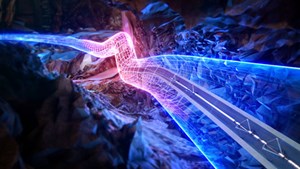
In many instances, poor placement of an ESP that could cause premature failure and/or equipment damage is the result of a low-quality wellbore, one drilled in a manner that caused areas of high dogleg severity and severe tortuosity to be present throughout its length. In such wells, the risk of placing the ESP in a sub-optimal location is high, especially when the only available data are from MWD equipment, as these data are far too limited in scope for proper decision-making. To rectify this issue and help operators ensure that they achieve proper ESP placement and better production from their wells, Gyrodata introduced the MicroGuide wellbore tortuosity logging system, the first of its kind in the oil field.
TECHNOLOGY
MicroGuide is a patented technology that generates wellbore tortuosity logs in conjunction with a gyroscopic surveying tool, or another service that provides comparable data. The system defines reference lines for the wellbore path, based on survey data, and determines displacements of the wellbore path from the reference lines. Through a series of calculations based on this information, the wellbore shape can be represented and visualized in 3D, allowing an operator to make critical decisions on well development and placement for artificial lift and other equipment, in line with areas of low tortuosity.
By collecting high-resolution data at 1-ft intervals versus the standard stand-length intervals of MWD tools, the technology reveals areas of high side-loading forces and high friction that would be otherwise invisible. Making decisions on optimized artificial lift system placement with previous solutions involved so many assumptions, and so much guesswork, that it ultimately resulted in a substantial number of unpredicted failures.
CASE STUDIES
Permian basin. An operator in the Permian basin drilled a challenging well and placed an ESP downhole as the method of artificial lift. After placing the pump, however, the operator found that there was damage to the cables, and the pump was failing prematurely. After pulling the pump, the operator decided to run Gyrodata’s wellbore tortuosity logs to better understand true downhole conditions and determine a placement for the ESP that would improve production and mitigate equipment damage.
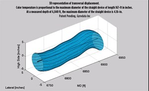
The wellbore tortuosity logs revealed that at the original placement depth, the primary cause of premature failure was severe tortuosity, with engineers recommending a new ESP placement at a depth of 6,840 ft, based on an analysis of the downhole data, Fig. 1. The operator worked closely with the service company’s engineering team to further analyze the well and found that a slight increase in placement depth (6,924 ft) would allow them to better balance production needs and the uniform bend restrictions of the ESP, due to wellbore geometry.
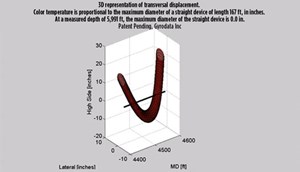
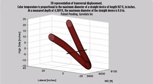
Gyrodata also revealed two additional areas of high tortuosity at measured depths (MDs) of 4,509 and 5,991 ft that would prove challenging when traversing the pump to the recommended set depth, Fig. 2. This allowed the operator to preemptively determine a means of getting to the recommended depth without damaging the equipment. Final ESP placement decreased energy costs and increased production while preventing future premature failures.
In another Permian project, an operator experienced a pump failure and intended to replace the damaged unit with a new ESP. The operator had struggled with premature ESP failures, due to cable and stator/armature damage brought on by traversing the wellbore to a less-than-ideal set depth, chosen on the basis of limited knowledge of wellbore quality from the MWD data. To reduce the risk of another pump failure and/or decreased production potential, the operator needed a detailed description of the wellbore and its complexities.
The wellbore tortuosity logging system was first run from 250 to 8,876 ft in the tubing before the damaged pump was removed. Afterward, the system was run again—from 250 to 9,518 ft—in the casing to log the entire wellbore. The analysis was performed, based on the operator’s specifications of a 6.28-in. casing ID, 6,276-ft installation depth, and ESP dimensions (5.62-in. OD, 60.54-ft ESP). The wellbore logs showed that from 250 to 2,000 ft and 4,000 to 6,000 ft, tortuosity was high enough to make proper ESP placement challenging. The analysis also revealed that at these depths, the maximum diameter of a straight device would be less than the 5.62-in. OD of the ESP. These results were confirmed with two sets of sensor data, giving the operator confidence in the system’s quality control.
The company then recommended an ESP placement deeper in the well, highlighting areas of the wellbore that could potentially cause issues when traversing the pump to the optimal set depth. The operator reduced the tubing size from 3½ to 2⅞-in., increased the number of cable clamps, and slowed the in-run speeds in troubled areas of the wellbore. By better understanding wellbore tortuosity and other downhole phenomena, the operator was able to successfully place the ESP at the recommended set depth without damaging it. The ESP is currently online and has been running for more than 300 days without issues.
Delaware basin. An operator drilled a well in the Delaware basin and determined a possible placement for its ESP as the method of production. The operator and ESP company wanted to place the pump at a shallower depth—which, though viable, would result in them potentially sacrificing production—due to their inability to determine a deeper placement with standard MWD data. To help the operator understand true downhole conditions and place the pump where production would be optimized without the equipment being damaged, a comprehensive wellbore tortuosity analysis was performed.
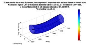
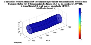
The wellbore tortuosity analysis showed that the first 5,000 ft of the well were without tortuosity, but immediately thereafter, there were several bends of approximately 1.7°. The analysis showed that the operator’s originally planned ESP set depth of 6,958 ft was in a location where tortuosity and sideloading force would not be of concern (Fig. 3), though based on completion design, this depth would also be unable to achieve the highest possible production level. Using only MWD data to make this decision, however, the placement made sense, as it was in a risk-free area downhole. Based on a more comprehensive understanding of the wellbore, Gyrodata recommended a deeper set depth at 7,650 ft to achieve optimized production, Fig. 4.
To get to the recommended set depth, however, would require the operator to traverse almost 700 ft of additional wellbore. To ensure that the operator could place the ESP at that depth without risking equipment damage or premature failure, Gyrodata provided the operator a full wellbore analysis to TD. Based on this analysis, there were two areas of significant tortuosity at 7,135 and 7,535 ft, which would make traversing the pump to the proposed depth challenging. In addition, an area at 7,557 ft had a 4° bend that would necessitate cable clamps to successfully pass the pump through. By understanding these concerns, the operator was able to work to proactively mitigate them. The solution would not have been clear with typical dogleg severity information and MWD data; had the operator proceeded as normal, it would have led to significant equipment damage when attempting to place the pump.
Midland basin. An operator in the Midland basin had previously experienced multiple ESP failures in a well, which were causing unnecessary downtime and costly equipment damage. Despite having several wells with little or no tortuosity on a previous pad, it was clear that this well would be a challenge from an operating and production standpoint. To ensure that they could understand the problems in the well and stop future ESP failures from happening, the operator decided to run wellbore tortuosity logs to collect detailed data on downhole conditions and wellbore quality.
Taking measurements in 1-ft increments versus stand-length intervals provided a detailed picture of true downhole conditions and issues that could be causing problems with the ESP. After obtaining high-density wellbore quality data from the logs, engineers determined that several spikes in wellbore tortuosity reported by the MWD data in the first 1,000 ft of the well, as well as two other incorrect spikes near 1,500 ft, MD, were incorrect, Fig. 5. Having this data meant that the operator could more effectively plan proper placement of the pump, as it wouldn’t wrongly believe that there was a difficult-to-traverse area in the shallowest parts of the well.
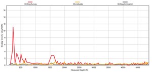
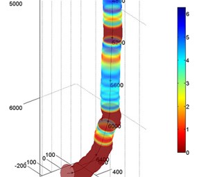
Had engineers used the MWD data, they would have implemented costly equipment to mitigate the supposed tortuosity and reach Gyrodata’s recommended placement point at 5,600 ft, MD. The company validated the proposed location with a 3D wellbore visualization, which verified that there was severe tortuosity deeper in the well that would make placing the ESP difficult or impossible, Fig. 6.
VALUE ADDED
While the energy industry continues to change, the need to achieve the best return on investment for operators stays very much constant. Complex wells with tortuosity and other downhole issues represent a major threat to profitability, as wells with low wellbore quality are more difficult to complete and put on production. As such, it is imperative that the industry understand the role that wellbore quality plays in meeting operational and financial objectives. Though the Covid-19 pandemic was a driving factor in commodity price stagnation, recent increases and balancing in prices means that operators now need to look at spending appropriately to address the challenges of drilling better wells and optimizing their production. The MicroGuide wellbore tortuosity logging system from Gyrodata is one way of ensuring that proper data on wellbore quality and the downhole environment are readily available, allowing operators to make better decisions on ESPs and artificial lift equipment placement that directly impact the bottom line.
- Shale technology: Bayesian variable pressure decline-curve analysis for shale gas wells (March 2024)
- What's new in production (February 2024)
- U.S. operators reduce activity as crude prices plunge (February 2024)
- U.S. producing gas wells increase despite low prices (February 2024)
- U.S. drilling: More of the same expected (February 2024)
- U.S. oil and natural gas production hits record highs (February 2024)
- Applying ultra-deep LWD resistivity technology successfully in a SAGD operation (May 2019)
- Adoption of wireless intelligent completions advances (May 2019)
- Majors double down as takeaway crunch eases (April 2019)
- What’s new in well logging and formation evaluation (April 2019)
- Qualification of a 20,000-psi subsea BOP: A collaborative approach (February 2019)
- ConocoPhillips’ Greg Leveille sees rapid trajectory of technical advancement continuing (February 2019)

