Driving toward safer, environmentally conscious offshore operations: Moving chemical storage to the seabed
Oil and gas operations have embarked on an industry-wide effort to identify and implement technologies and processes that support the transition to a low-carbon society. As offshore installations explore various options to reduce or eliminate conventional methods that generate pollution, or create hazardous environmental situations, the electrification of oilfield equipment has emerged as a viable solution for reducing carbon footprint. As a result, an increasing number of offshore field developments are being planned with the electrification of oil and gas operations in mind, thereby increasing the desire to have key processes—such as the supply and injection of chemicals—located as close to the wells as feasible.
Electrification of subsea equipment entails replacing the fossil-based power supply with renewable energy, which will support the transition to a low-carbon society. The industry shift for smarter, more environmentally friendly energy production has opened the need for new, innovative subsea technologies that must answer the current challenges of safely managed remote operations; carbon emissions; risk and cost of field development.
WHY SUBSEA STORAGE?
As production rates have increased exponentially over time, the industry has discovered the benefits of subsea storage systems. Nearly two decades ago, these systems were introduced to store hydrocarbons in a subsea environment. The focus was to design a solution with a low environmental footprint that takes advantage of the limitless seafloor space. The technology provides a competitive, economically feasible alternative to conventional practices.
Engineering and testing activities have proven that it’s possible to operate a subsea storage unit with a flexible membrane that defines the horizontal interface between oil and seawater. Therefore, the membrane eliminates the problems of emulsion-layer buildup and bacteria growth found between oil and seawater in the initial subsea storage solutions. The development of oil/condensate storage technology allows for adaption to use a membrane-based subsea storage solution that’s modified to store chemicals, as well as clean energy, in the form of liquid ammonia.
Chemical injection into wells enhances flow assurance by greatly reducing the buildup of substances that can block the passage of wellbore fluid, such as hydrates, wax and scaling. In doing so, the viability for developing remote fields by means of a long-distance tie-back to an existing host facility or subsea infrastructure is significantly increased.
The conventional method of using a dedicated methanol or monoethylene glycol (MEG) pipeline or tubes within a large integrated services umbilical, to deliver the necessary chemicals for long distances, is extremely costly, both in terms of CAPEX and OPEX. Alternatively, it is possible to gain greater efficiency and economical value using a subsea chemical and injection storage unit and a simple power cable. In fact, in the next five years, the need for a power source from a host many miles away will be made redundant by new technology that allows direct at-source power.

NOV designed a subsea energy and liquid storage system to serve as a singular technology that allows the possibility for three different storage systems: oil/condensate, chemicals, and ammonia, Fig. 1. Within the storage system portfolio, the subsea chemical storage and injection (SCSI) technology allows simplified distribution architecture. This eliminates the need for an expensive umbilical, especially in the case of marginal fields and/or stranded reserves.
In greenfield applications, the implementation of subsea storage technologies moves chemical storage from the topside facilities to the seafloor. Unmanned production platforms or not-normally-manned platforms call for eliminating the need for on-deck personnel to maintain equipment and generate positive field economics, which is especially relevant for shallow-water deployment. The relocation of large chemical storage to the seafloor will help achieve the industry objective of reducing personnel on offshore facilities. This will drive down HSE incidents, reduce CO2 discharge to the environment, help eliminate the risk of personnel exposure to toxic chemicals, and minimize topside space and weight.
An energy-efficient subsea storage system with a reduced environmental footprint has become a competitive alternative for future and existing field developments. The subsea energy and liquid storage technology utilizes a flexible membrane to provide safe chemical storage at ambient hydrostatic pressure. The membrane is designed for compatibility with commonly used chemicals to support subsea production systems in their day-to-day operations. Previous engineering and testing have shown a need for large subsea storage units, ranging in size from 1,600 to 350,000 ft3 (45 to 10,000 m3), and these large subsea storage units will provide a unique flexibility for field development.

HOW THE SCSI DESIGN WORKS
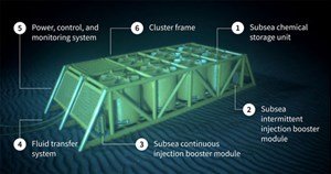
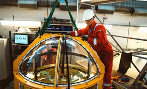
The SCSI system (Fig. 2) consists of storage units designed to store buoyant, neutral and nonbuoyant production chemicals, ranging from inhibitors to preservation chemicals. Each unit contains one type of chemical, with the overall storage volume being dictated by chemical consumption rates and refill intervals. The flexible rubber membrane is protected and secured to the frame by an external composite protective structure. This membrane is designed to safely keep the stored fluid within the membrane during the service life. An elastomer-coated fabric test program has been established, with focus on aging tests and subsequent characterization tests, as well as other material qualification tests that might be relevant for the membrane qualification, Fig. 3.

Generally, steel, concrete, and fiber-reinforced plastic (FRP) are all feasible construction materials for the protective structure, but the use of lightweight, corrosion-resistant FRP allows for easier, more cost-effective deployment and intervention while providing a design life of more than 30 years. FRP material also offers high energy absorption when struck by a dropped object.
The SCSI units come in several sizes to accommodate various storage requirements for different chemical types. Examples include a 1,600-ft3 (45-m3) unit for storing production chemicals injected in ppm concentrations, or a 10,000-ft3 (300-m3) storage unit, used primarily for hydrate inhibition. Field studies conducted with operators have shown that larger subsea storage units provide significantly greater flexibility with regard to commissioning (e.g. opportunity for shorter period) and refilling logistics. Sensitivities that have been evaluated include a combination of different chemicals and injection rate requirements: MEG, methanol, scale inhibitor, asphaltene inhibitor, antifoam, diesel, kinetic hydrate inhibitor, H2S scavenger, and emulsion breaker.
The main SCSI system consists of the following elements: chemical storage units, injection booster modules, a fluid transfer system (refilling system, isolation system, control, instrumentation, and power supply from topside/shore), and a cluster frame. Storage units and boosters are individual components for each chemical, and the cluster frame is a steel structure containing all the main components. Due to the modular design, scalability of the system is simple, which allows consideration to also be used on existing offshore assets that have limited topside space. The SCSI system has been designed with standard, well-known intervention and maintenance procedures in mind. This provides additional flexibility for operators, as they do not have to wait for optimum environmental conditions to conduct loading and offloading activities, which are required for a fixed asset.
Similar to topside storage operations, chemical volumes must be regularly refilled and monitored in the SCSI unit during the field’s life. Depending on the field requirements, different refilling operations are available. The most common options include refilling by use of downlines attached to the supply vessel, storage unit change-out, refilling by use of downline attached to a buoy, or refilling by use of a refilling tank. Refilling operations and logistics are evaluated, based on parameters such as environmental conditions, time, water depth, vessel specification, cost, HSE, and whether any planned maintenance is to be undertaken.
The SCSI system is designed with three safety barriers to protect the equipment, as is common for all process installations with a potential for external or internal over-pressurization of process pressure-containing components. The three safety barriers—a process control system, a process shutdown system, and a pressure safety relief valve—are independent of each other, which means there are minimal or no common failure modes between the three safety barriers. There will be adequate margins, both in time and pressure levels, between actuation of safety barriers to achieve the intended safety function.
SUPPORTING RENEWABLE ENERGY
With availability for water depths greater than 328 ft (100 m), the properties of membrane-based storage can store clean energy in the form of liquid ammonia as a hydrogen energy carrier. Examples for end usage are power storage for offshore assets; offshore fueling stations for ships; renewable energy storage with offshore wind turbines; or common storage of ammonia for fertilizer plants.
Today, ammonia is stored onshore, either in pressure vessels for smaller volumes or frozen to -27°F (-33°C) for large volumes. Ammonia is a highly toxic chemical, which, when released into the air, emits vapor gases that pose a risk in today’s onshore storage facilities. NOV’s subsea energy and liquid system has a dual barrier against potential leakage paths, with the first barrier being the membrane and the second barrier being the outer composite shell with integrated isolation valves. Since the combination of pressure higher than 145 psi (10 bar) and temperatures lower than 43°F (6°C) keeps ammonia in a liquid state, the seafloor is an ideal environment for the economical storage of ammonia in liquid form while providing protection for both rig personnel and marine life.
The full system solution will encompass storage units placed near the platforms at safe water depths, with riser systems providing fuel to the ammonia power generators and the refilling systems.
Additionally, producing ammonia from renewable resources could have a lot of potential moving forward. In a February 2021 presentation, the American Bureau of Shipping (ABS) noted that a total of 30% of a shipping fleet could be powered by ammonia by 20501 . As similar alternatives continue to grow, a safe and economical solution for ammonia storage will be necessary.
JOINT INDUSTRY EFFORT
Many major oil and gas operators have global initiatives to reduce emissions for new or existing assets. The subsea energy and liquid storage system can be an important building block to both green and brownfield developments.
The novel technology elements in the SCSI system have been identified, based on a systematic, risk-based approach. Based on the technology assessment, a Technology Qualification Program (TQP) has been established for the subsea energy and liquid storage system, which provides the development state and necessary qualification activities for the following storage systems: subsea storage of oil/condensate, SCSI system, and subsea storage of ammonia.
The TQP objective is to qualify all subsea storage systems for the subsea market by fourth-quarter 2022, and the completed qualification program aims to reach a technology readiness level (TRL) of 4: Validation of Product. The TRLs are based on a scale from 0 to 7, with 7 being the most mature technology. The proposed qualification activities are intended to provide a solution with high reliability, as well as satisfactory performance and safety, challenging the failure modes for the range of conditions expected in operation.
As a part of the TQP in fourth-quarter 2022, ABS will be confirming the ability of subsea energy and liquid storage technology to perform its intended functions in accordance with defined performance requirements. This includes evaluating technical risks and uncertainties associated with the proposed technology. The proposed TQP includes a five-stage process compatible with API RP 17N/Q, and ISO 16290. This five-stage process will be used together with the ABS Guidance Notes on Qualifying New Technologies2, and at the end of the qualification work, an ABS Statement of Maturity will be issued.
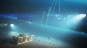
Equinor Energy, OGTC, and NOV have completed a detailed engineering phase of a joint-industry project for a subsea oil/condensate storage system, with the goal of building a large-scale prototype for final qualification and product validation testing. All technology elements will be qualified, either as part of a large-scale verification using a 7,000-ft³ (200 m³) test storage unit or as part of a small-scale verification, using smaller test storage units of 100 ft³ (3 m³). The submerged test activities in the qualification project are planned to be performed at Equinor’s K-Lab test facilities in Norway.
Our industry is most certainly seeing a transition to electrification, marginal fields, and longer tie-backs. Technical innovation and the adoption of new ideas in the subsea space will help ensure the changeover to novel processes is both affordable and competitive. As a disruptive technology, subsea energy and liquid storage promises new paradigms that will usher in cost-effective, environmentally conscious solutions for the traditional and renewable energy sectors .
REFERENCES
- “Understanding where ammonia fits in,” American Bureau of Shipping, René Sejer Laursen and Joshua Padeti, Houston, Texas, Feb. 11, 2021.
- “Guidance notes on qualifying new technologies” American Bureau of Shipping, April 2017
- Advancing offshore decarbonization through electrification of FPSOs (March 2024)
- Subsea technology- Corrosion monitoring: From failure to success (February 2024)
- Driving MPD adoption with performance-enhancing technologies (January 2024)
- Digital transformation: A breakthrough year for digitalization in the offshore sector (January 2024)
- Offshore technology: Platform design: Is the next generation of offshore platforms changing offshore energy? (December 2023)
- 2024: A policy crossroads for American offshore energy (December 2023)
- Applying ultra-deep LWD resistivity technology successfully in a SAGD operation (May 2019)
- Adoption of wireless intelligent completions advances (May 2019)
- Majors double down as takeaway crunch eases (April 2019)
- What’s new in well logging and formation evaluation (April 2019)
- Qualification of a 20,000-psi subsea BOP: A collaborative approach (February 2019)
- ConocoPhillips’ Greg Leveille sees rapid trajectory of technical advancement continuing (February 2019)


