Uniform fracture growth using engineered solid particulate diverters
Hydraulic fracturing is an essential tool for economic production from low-permeability reservoirs. However, upon stimulation, these reservoirs typically experience an initial high production rate but fast decline within few months after reaching peak rate and usually results in low recovery efficiency especially in unconventionals. This type of production decline has been commonly observed in different plays around the world, including the Barnett and Vaca Muerta. These practices also revealed that only limited number of planned clusters contribute to overall production.
As statistically analyzed on multiple wells from different unconventional plays, nearly one third of the planned clusters might not be active and cannot flow back any hydrocarbon, due to their low hydraulic fracturing efficiency. For these non-productive clusters, the hydraulic fractures cannot be created or fully propagated into the far-field region and hence the number and extent of developed fractures is much smaller than expected. This anomaly can be mainly attributed to the hydraulic fracture initiation and propagation in the near wellbore vicinity. Operators have been searching for practical solutions to fully understand this unexpected phenomenon and to maximize sweep efficiency and hence overall production from their assets. The variation of fracture potential, which is a complex function of multiple geomechanical and reservoir properties, could change the fracture initiation and propagation.
SOLID DIVERTING AGENTS
Field observations and 3D numerical simulations suggest that a complex hydraulic fracture geometry can be developed in the near-well region. To achieve these objectives, solid diverting agents have been adopted to effectively block existing fluid entries to guide the fluid distribution in fracturing and re-fracturing treatments for unconventional reservoirs. A state-of-art particulate diverter system has been developed and widely used in in-well fluid diversion treatments, including hydraulic fracturing and matrix acidizing. Unlike the existing techniques and diverters, the next-generation particulate diverters can be engineered properly for in-stage diversion and tightly-spaced fractures generation with time efficiency and their self-degradation capabilities can save the cost and time for the removal of these temporary seals.
To ensure the success of particulate diverters in fracturing and re-fracturing operations, the particulate diverting agents need to be optimized, according to the reservoir and wellbore conditions. To achieve this goal, a full understanding of the underlying mechanism of jamming and plugging is recommended, which can eventually be beneficial to the particle design and pump strategy of the chosen particulate diverters. Based on the physics and diverter mechanical properties, a comprehensive design workflow was introduced to guide the design and usage of particulate diverters.
JAMMING/PLUGGING PROCESS
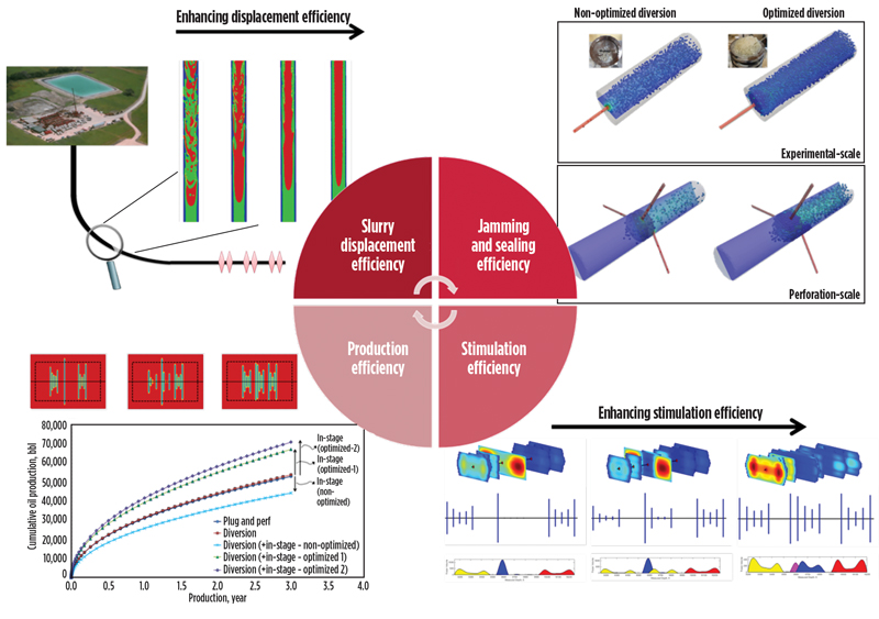
To build on previous work, engineers focused on the influence of solid particle design on the jamming and plugging process and the associated fracturing efficiency. The new analysis showed that the emerging diverters enable creation of additional flow channels from inert clusters, and therefore the conductive reservoir volume can be increased upon fluid diversion treatment.
Methodology and workflow. Integrated geomechanical analyses were conducted to evaluate and optimize the particulate diverter application in re-fracturing. Engineers used computational fluid dynamics/discrete element method modeling (CFD-DEM), and a 3D fracture simulator to model particle transport, fluid diversion and associated re-fracturing processes. Overall conductive reservoir volume and associated production were forecasted to compare different design scenarios under local reservoir and wellbore conditions. CFD-DEM was used to model particle slurry transport during injection and successive plugging in the fluid diversion process.
These coupled CFD-DEM models are capable of simulating particle-particle, particle-fluid and particle-opening interactions, which dictate the diverter slurry displacement and plugging phenomena, Fig 1.
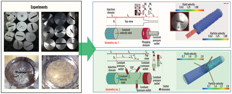
These models have been calibrated against experimental data with various particle characterizations, opening geometries, fluid rheology, and pumping conditions. The calibrated CFD-DEM engine can be customized to optimize the flow conditions and diverter characterizations required for specific field executions.
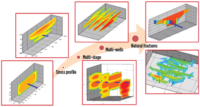
A 3D hydraulic fracture propagation simulator, used in combination with other modeling programs, determined that both dynamic fluid flow and pseudo-static particle deposition are involved in the fluid diversion process. Considering the complexities of the underlying mechanisms and availabilities of the modeling tools, an engineering design workflow and integrated analysis of particulate diverter applications is proposed, which is comprised of four major steps, Fig. 2.
PARTICLE DESIGN
The service provider elected to focus on screen particle design to identify the influence these designs would have on stimulation efficiency in a re-fracturing application. In a fluid-diversion treatment with solid particles, the diverting agents should be mixed with carrying fluid at the surface facilities. Then, the well-mixed slurry is pumped into a wellbore and can flow into any open flow channels that it passes by. When moving through these openings, the diverting agents can deposit from the carrying slurry to form jammed structures at the mouth of the openings. Following this, additional layers of solid particles can be progressively settled from particle-laden slurry to bridge-off the flow channels and limit the passage of stimulation fluid.
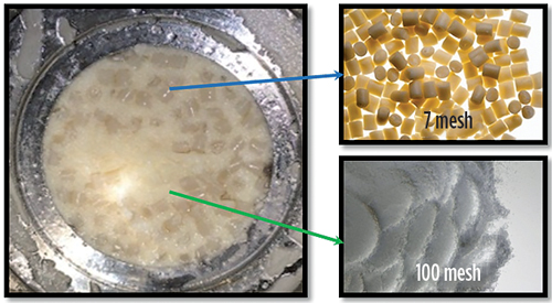
In this way, stimulation fluid would be forced to move into challenging regions where they do not normally go. Both dynamic fluid flow and particle accumulation are involved in fluid-diversion process. Derived from extensive investigations, our understanding of the jamming and plugging mechanisms are summarized in this section. According to our findings, a solid bi-particle degradable system is selected as a temporary diverting agent for fluid diversion. In this study, two distinct sized particles comprise the diverter pills, Fig. 3.
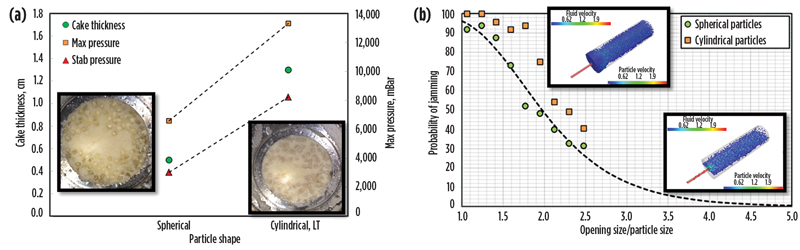
In new experiments, the mixture of these particles were shown to effectively plug the mouth of an opening and create a temporary seal with the integrity to withstand pressures necessary for redirecting stimulation fluids. As observed from experimental and numerical analyses, fundamental physics governs the jamming and subsequent plugging of exit opening with the bi-particulate system for fluid diversion. In this progressive sealing process, the relatively large particles are mainly used to block the opening with the formation of a stable jammed structure. And then the smaller ones can be stranded and accumulated within the void space between larger particles to reduce the porosity and permeability of the jammed structure. In this way, a temporary plug can be created to restrict fluid flow passing through the opening. Engineers investigated the probability of creating a stable jammed structure, which is a prerequisite for subsequent plugging process. For this binary particle system, Fig. 4., shows that the particle size and shape could dictate the stability and efficiency of the jamming process. Once the successful jammed structure is created, it can be sealed for expected pressure buildup and fluid diversion.
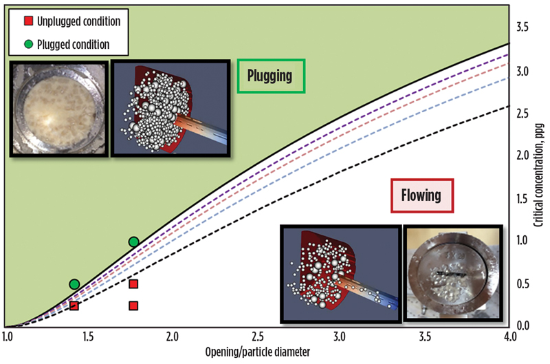
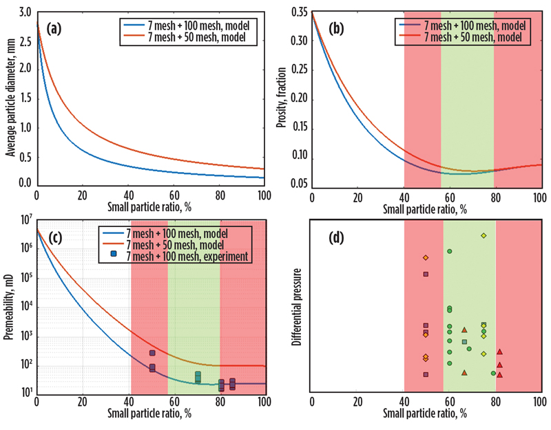
To assess the associated sealing efficiency, different data sources were employed to determine the efficiency of jamming and sealing processes and were cumulatively evaluated in the engineering design for bi-particle diverter systems. The binary mixture can effectively jam the opening, build-up fluid pressure and mitigate the fluid flow resulted from its optimal packing, where the fraction of small particles plays an important role. For actual case scenarios, the design recommendations, which define the favorable conditions associated with mechanical stability (jamming) and pressure build-up (sealing), can be generated by running coupled CFD-DEM simulations and analytical models. Depending on the required differential pressure and opening geometries, the engineering design of the proposed diverter system can be manipulated and optimized to ensure the effectiveness of fluid diversion.
CASE STUDY
A 3D fracture simulator (CFRAC) was used to model the fracturing process based on the selected particle designs. The overall conductive reservoir volume, and the corresponding production, were forecasted to contrast the fracturing efficiency between different design scenarios.
A geomechanical model was set up based on a data set obtained from a hydraulically fractured horizontal well. The wellbore was constructed in a tight-gas reservoir in South America, which was drilled in a minimum horizontal stress direction (325°) with an average permeability of 0.1mD and a pore pressure gradient of 0.5 psi/ft.
- Initial design (10 stages with 9 clusters/stage). Base Case: Conventional mechanical isolation between stages (plug-and-perf operations). Increased Production Case: Particulate fluid diversion between stages (intra-stage diversion).
- Modified design (5 stages with 18 clusters/stage each). Increased Efficiency Case: Conventional mechanical isolation between stages (plug-and-perf + next generation engineered particulate diverters). Combination Case: Particulate fluid diversion between stages (plug-and-perf + next generation engineered particulate diverters + in-stage next generation engineered particulate diverters.
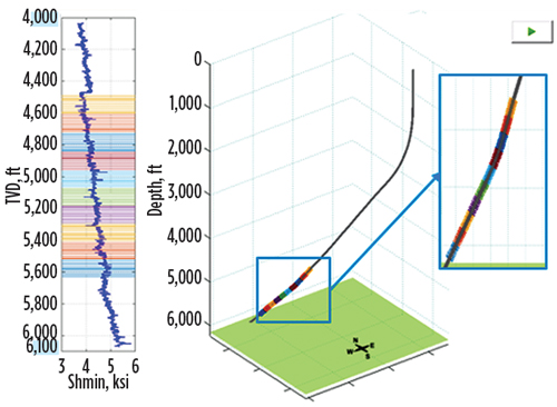
In the initial completion design, there were 10 stages with 9 clusters per stage, Fig. 5.
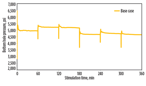
In this research work we analyzed 6 stages. Initially in the original design (base case) plug and perf operations was used with 60 min. of injection per each stage at a rate of 65 bpm. At each stage we observe slight increase in pressure due to plug and perf diversion method, Fig. 6.
A sensitive analysis was performed to quantify the impact of completion design and pumping strategy on the resulted stimulation efficiency and overall conductive reservoir volume. In the sensitivity analysis the mechanical isolation technique (plug and perf) for diversion was replaced by next generation particulate diverters. At each stimulation stage (intra-stage diversion) engineered design was used to calculate the concentration of these diverters. Comparing the predicted pressure response for both scenarios, it is evident the diversion has been more effectively implemented using next generation particulate diverters, Fig. 6 and Fig. 7.
The pressure increases at each stage due to presence of particulate diverters is higher compared to the conventional mechanical isolation technique. To understand the fractures generated, stimulation efficiency we analyzed the distributed fluid volume in each cluster which will help us understand the overall conductive reservoir volume in each case.
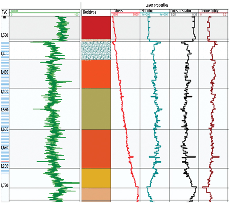
Figure 8 compares the distribution of total volume of fracturing slurry between six stimulated perforation stages under different design scenarios. For the non-engineered design (base case), less fractures are created from the initial clusters in stages 2, 3 and 5 as compared to the engineered design case (increased production case). For the improved case (increased production case), fractures could be initiated and extended from the three clusters placed in stage 2. This engineered design was suggested based on the characterizations of the diverter system and wellbore condition. Only a small quantity of fluid passing through the placed diverter pack can cause significant differential pressure and effective fluid diversion. Therefore, all the fluid could be diverted into the non-active clusters to fracture the un-stimulated region. If all the energy is properly utilized, additional fractures can be developed to maximize the conductive reservoir volume and hence increase the production.
Modified design (5 stages with 18 clusters/stage each). The engineering team studied the effect of combining two stages into one stage to reduce the total number of stages (2-hr injection per combined stage @ 65 bpm), however, the total number of clusters is kept the same as the initial design, Fig. 9.
To increase the efficiency of plug and perf technique, the engineering team employed next generation particulate diverters and the predicted pressure response for “increased efficiency case,” Fig. 10a.
It is a clear improvement in efficiency over the original (Fig. 6.) base case. Figure 10b is a predicted pressure response from a modified design which uses plug-and-perf + next generation particulate diverters + in-stage next generation particulate diverters. Examination reveals the diversion has been more effectively implemented using next generation particulate diverters. To understand the fractures generated, stimulation efficiency, engineers analyzed the distributed fluid volume in each cluster which helped determine the overall conductive reservoir volume in each case.
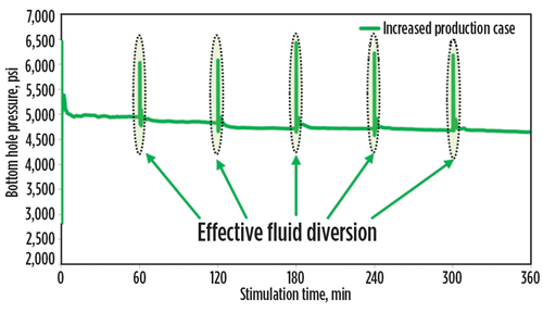
Figure 11 compares the distribution of total volume of fracturing slurry between six stimulated perforation stages under two different design scenarios. For the non-engineered design (base case), less fracture is created from the stages 1, 2, 3 and 4 as compared to modified design case (increased efficiency case) with using engineered particulate diverters. For the modified design case (increased efficiency case), more fractures were created as deduced from the additional volume of fluid distributed in “increased efficiency case”. This engineered design was suggested based on the characterizations of the diverter system and wellbore condition. Only a small quantity of fluid passing through the placed diverter pack can cause significant differential pressure and effective fluid diversion. Therefore, all the fluid could be diverted into the non-active clusters to fracture the un-stimulated region.
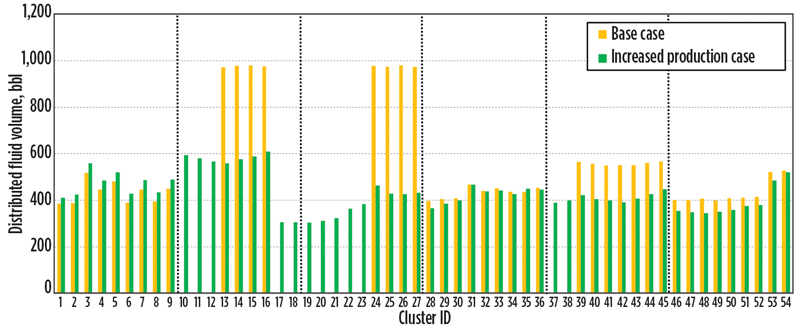
Figure 12 compares the distribution of total volume of fracturing slurry between six stimulated perforation stages under two different design scenarios. For the non-engineered design (base case), less fracture is created from the stage 2, and 3 as compared to combination case. For the combination case, additional fractures were created as deduced from the additional volume of fluid distributed. This engineered design was suggested based on the characterizations of the diverter system and wellbore condition. Only a small quantity of fluid passing through the placed diverter pack can cause significant differential pressure and effective fluid diversion. Therefore, all the fluid could be diverted into the non-active clusters to fracture the un-stimulated region. If all the energy is properly utilized, additional fractures can be developed to maximize the conductive reservoir volume and hence increase the production.
CONCLUSION
The broad varieties of reservoir conditions demonstrate the need for fluid diversion in fracturing. In this way, the fracture contact area is enhanced to uniformly drain the reservoir by applying additional fluid diversion treatments. The feasible engineering solution is to properly design diverter application pills to temporarily send the fluid into designated zones for fracturing. As demonstrated from this work, multiple design aspects can dictate the success of diversion treatment, including particle size, shape, ratio, concentration and degradation profile. The selected particle design is recommended based on the underlying mechanism of particle jamming and sealing.
The next-generation particulate diverter system and the associated design workflow enable engineers to design and customize a particulate diverter system for effective fluid diversion. If engineered properly, solid diverting agents could be progressively settled from diverter-laden slurry and create stable plugs to bridge off active flow channels, which could be perforations, sliding-sleeves, wormholes, natural fissures or drilling-induced fractures. This approach delivers the required diverter characteristics to ensure the formation of stable jamming and sealing structures, when subjected to specific well conditions.
The integrated engineering design workflow can guide the particle design and application in fracturing operations. The fluid diversion, and hence fracturing efficiencies, were evaluated between engineered and non-engineered operational designs. As indicated from these comparisons, the optimized design can be achieved, which in turn allows for successful diversion of the fracturing fluid into the target zones to create additional fractures.
The fracture treatment case study demonstrated the particle design can be engineered to enhance diversion efficiency and optimize the usage of diverters. The presented design workflow and analysis will better enable operators to design and customize solid particles for efficient fluid diversion. Finally, the engineered design workflow can also be prospectively extended for re-fracturing as well as acid fluid diversion for matrix acidizing.


- Regional Report: Brazil reaches for new heights in 2026 (March)
- What's new in production: Things go better with Coke (February)
- Before OPEC, there was Texas: A better path for Venezuela’s oil revival (February)
- International E&P shows the way forward (February)
- The benefits of Simulfracs (January)
- Molecular fracing: A rock-focused, field-ready stimulation chemistry (January)
- Subsea technology- Corrosion monitoring: From failure to success (February 2024)
- Applying ultra-deep LWD resistivity technology successfully in a SAGD operation (May 2019)
- Adoption of wireless intelligent completions advances (May 2019)
- Majors double down as takeaway crunch eases (April 2019)
- What’s new in well logging and formation evaluation (April 2019)
- Qualification of a 20,000-psi subsea BOP: A collaborative approach (February 2019)

