Quality and reliability: Finding the balance
An end-user may perceive a product to be “high quality,” because it has performed reliably. Conversely, the product may be considered “reliable,” because its materials and workmanship are of high quality. In fact, equipment quality is a prerequisite for reliability.
Historically, our industry has focused heavily on quality. Decades ago, original equipment manufacturers (OEMs) began implementing standards for quality systems, based on British Standard 5750 and ISO 9001. These standards provided the criteria for proactively ensuring quality, monitoring for conformance to requirements, and elevating the quality of equipment. Today, most OEMs have implemented API Specification Q1, which defines quality management system requirements for manufacturing organizations in the oil and gas industry.
Operators articulate requirements for quality more frequently than for reliability. However, some operators are beginning to include reliability requirements in their tenders for high-risk offshore projects. These requirements are usually expressed in terms of a minimum service life, a mission profile, and material options considered appropriate for well integrity.
Quality and reliability are related concepts. Quality can be defined as conformance to requirements; the lack of variation in manufactured components; or repeatability. In practice, quality assurance (QA) is achieved through quality control (QC) processes, which monitor all relevant activities for compliance with quality requirements. Typical manufacturing QC processes include component dimensional measurement, factory acceptance test (FAT), and raw material checks.
Completion equipment must be manufactured, using quality requirements that are appropriate for application risks. But what is appropriate? An OEM may choose to manufacture most of its equipment to a minimum quality level (QL). Minimum QL requirements are known to satisfy risk and quality requirements for most end-users. When the minimum QL is insufficient, an operator will order equipment to its quality requirements. During manufacturing, these requirements will supplement the OEM’s minimum QL.
Reliability also has multiple definitions, including the probability that an item will perform a required function without failure under stated conditions for a stated period of time; and the number of failures over a period of time (hazard rate).
Equipment reliability begins with design for reliability (DfR). DfR ensures achievement of repeatable performance over time, or service life. Key elements of a robust DfR program include:
- Design policies and guidelines
- Simulation and testing programs
- Reliability assessments
- Failure modes and effects analysis (FMEA) or failure modes effects and criticality analysis (FMECA) programs, and
- A failure reporting and corrective action system (FRACAS program).
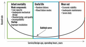
- Service life is the time over which the equipment is expected to perform. Unplanned changes in the downhole environment, such as changes in a well acidizing program, can shorten service life. A primary goal of any DfR program is to minimize infant mortality and maximize useful life. In Fig. 1, shows how the hazard rate declines during the period of infant mortality, stabilizes during useful life, and begins to increase during wear out.
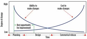
Operation within specification is the basis for reliability estimates made during equipment development. Limits considered in reliability estimates may include: recommended tubing and casing size; published ratings for temperature, pressure tension and torsion; and environmental limits for exposure to hydrogen sulfide (H2S) and carbon dioxide (CO2). A DfR program also enables mitigation of equipment problems early in development, while it is cost-effective to implement changes, Fig. 2.
Finally, a key element in any reliability system is the feedback process for identifying, documenting and reporting product failures after delivery to the end-user. For OEMs, FRACAS programs meet this requirement, and lead to organizational learning and improvement.
Managing equipment risk in completion projects. Operators manage many types of risk in their projects, including financial, schedule, safety and operational risks. In addition, the operator shares some equipment risk with the OEM. Components of equipment risk include performance, interfaces, installation, service life, and survivability.
Many risks associated with performance are effectively managed, using industry equipment standards such as API 11D1, 14A, and 19AC. These standards provide standardized methods for verification and validation. However, discovery of risks associated with interfaces and installation frequently require the use of an FMEA or FMECA process.
Service life is influenced by material and configuration stability. In addition, operators and OEMs can use industry standards, such as NACE MR01-75 (ISO 15156) for the selection of materials. When configuration stability cannot be adequately assessed using equipment standards, OEMs may conduct service life simulations.
Laboratory testing can assess some aspects of survivability, but cannot reproduce well path tortuosity. The high mechanical loads that result from traversing tortuous well paths often lead to mechanical damage or premature component actuation. Historically, product survivability in tortuous well paths was studied using two-dimensional methods, or proven while running the completion. Progress is being made in assessing for survivability, using wellbore geometric simulation. The operator bears most of this risk.
HPHT completion projects are inherently high-risk and extremely expensive. In addition, the project cycles are very long. Application risks include safety, environmental, and well control incidents. Customization of HPHT equipment for each application requires a large commitment of personnel and infrastructure by the OEM and operator. The cost of equipment failure is very high. Operators who perform HPHT completions in U. S. offshore waters must follow a process mandated by BSEE. A key decision point in this process is known as “fit-for-service” (FFS). Equipment that is fit-for-service must first be fit-for-purpose (FFP).
The FFS process accounts for individual well application variables (site-specific), of which only the operator has sufficient knowledge. Although the operator ultimately bears all completion risk, the FFS process helps mitigate the equipment risk.
By comparison, zonal isolation in multi-zone horizontal wells on land has lower safety, environmental and discharge risks. In these applications, frac plugs or open-hole packers with sliding sleeves, are used to isolate the stimulated zone from all other zones. In North America, such wells can have 50 or more zones. The primary risks associated with failure of zonal isolation equipment include inadequate or no stimulation of the target zone, coupled with over-stimulation of previously stimulated zones.
Failure of zonal isolation equipment leads to unplanned intervention expense and interruption of the well manufacturing process. Operators consider the following criteria for managing equipment risk in zonal isolation:
- The application history of the OEM/supplier’s equipment
- Knowledge of the OEM’s quality system
- The reputation of the OEM/supplier’s service organization.
Innovation in zonal isolation equipment has occurred at a rapid pace, resulting in product life cycles of three years or less. Such rapid product development schedules make it very challenging for OEMs to fully assess the reliability of new equipment prior to market introduction. Straightforward laboratory pressure and temperature tests in oilfield casing or fixtures serve to validate the performance of most zonal isolation equipment. Survivability confirmation still occurs through field installations, so an operator usually accepts some survival risk with new equipment, as long as it can deliver continual improvements in performance, durability and pricing.
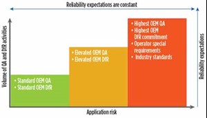
Two examples of optimized quality and reliability. Regardless of the QA requirements, the DfR methods used and the application risk, operator expectations for reliability are always high. Fig. 3.
The following examples describe two types of completion equipment developed for very different applications. Both were optimized for performance requirements, manufacturing to high-quality standards, and minimizing equipment risk for their respective applications.
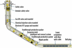
Long service life product. The downhole wet connect system for fiber-optic (FO) deployment is a customizable, low-volume, long-service-life product that enables an operator to run an upper FO completion independently of the lower FO completion, and connect the optical fibers (a “wet connect”) in the downhole environment, thousands of meters from the rig floor. The optical fibers are +/–.010 inches thick (.250 mm). A human hair is .003 inches (.080 mm) in diameter. The system of packers and FO accessories enables the operator to visualize the entire wellbore. Figure 4 shows a typical wet connect completion schematic.
BHGE’s wet connect product was recently updated for a North Sea application, taking into account application risks that included well control and equipment survivability. The tortuosity of the planned wells required numerous torque and drag simulations. The operator chose to use one of BHGE’s internal quality levels for manufacturing QA and articulated its reliability requirements, which included a service life target and risk assessment activities. Extensive DfR activities were used for mitigating equipment risk:
- Design FMEA conducted by BHGE, with operator review/endorsement
- Laboratory test program to verify configuration stability
- Installation pFMECA conducted by the operator with BHGE participation.
Project duration was approximately two years. The wet connect product was run recently in the North Sea well and demonstrated 100% mechanical and optical performance.
Short service life product. Degradable frac plugs are short-service-life equipment developed for the plug-and-perf market, in which dozens of operators participate. The plug is conveyed using the pump-down method and isolates previously stimulated zones against stimulation pressures. The pressure requirement for frac plugs in this market is typically 10,000 psi, and the service temperature can vary between 120°F and 350°F. Degradable frac plugs must survive well tortuosity during conveyance, remain stable to perform the sealing mission, and then degrade at a pre-determined time, post-stimulation. The degradable feature negates the need for coiled tubing millout operations. Extensive DfR activities were used to mitigate risk in this equipment:
- Use of a proven frac plug configuration
- Design FMEA for the plug, and process FMEA for its assembly
- Full-scale plug test program, including rate of degradation (RoD) testing.
Manufacturing volumes for the degradable frac plugs are very high. They are subject to the BHGE completions and well intervention product line’s standard quality level program, which is considered appropriate by BHGE for application risk.
A portfolio of plug sizes was developed over approximately five years, and an extensive portfolio of degradable materials was created that enables degradation to be customized for the operator’s application. A sophisticated, vertically integrated manufacturing organization also was created to control component quality and plug reliability. The FRACAS system estimates that the degradable frac plug portfolio has a reliability of 99.7%. This confirms that a robust DfR program leads to high reliability, using standard quality requirements. WO

