Test program yields shale-optimized casing connections
Before 2002, connections designed for drilling and completions were tested at the discretion of a specific manufacturer. There was no consistency and each manufacturer, at times in partnership with an operator, developed its own testing procedures. The lack of standards made it hard to compare connection performance, safety and reliability.
In the fourth-quarter of 2002, the first widely recognized testing protocol for casing and tubing connections used in the petroleum and natural gas industries was released. The International Organization for Standardization (ISO) and the American Petroleum Institute (API) collaborated and released identical standards under the titles ISO 13679 and API RP 5C5, respectively. Most major premium connection manufacturers adopted these protocols for their new connection development.
The test procedure implemented a range of Connection Assessment Levels (CAL I–CAL IV), with increasing stages of severity to account for different criticality levels. Each level required multiple test specimens, with connection configurations that tested the limits of manufacturing tolerances, to account for worst-case scenarios for galling and sealability performance for each design. The CALs applied a range of rigorous testing cycles that simulated downhole conditions, which included extremely high formation pressures and temperatures up to 356°F.
GULF OF MEXICO INCIDENT
After the Deepwater Horizon event, regulations on safety and reliability for all drilling and completions components became significantly more stringent. Subsequent versions of ISO/FDIS 13679 added increasingly severe testing criteria and the previous CALs of the 2002 version were much harder to achieve. Although these revisions came in 2009 and 2011, they never moved past the draft stage due to lack of joint agreement in the industry. Regardless, the 2011 version was widely adopted to qualify most of the premium connections on the market today.
In 2017, API released its next version of 5C5, but it was no longer a collaboration with ISO 13679, as it was in the past. This standard introduced cyclic yielding and worst-case discharge. Both are conditions that can be experienced in offshore environments with high pressure formations or in extremely cold environments, such as deep water or the Arctic.
Despite the changes and increasingly rigorous protocols, the testing methods fail to consider the unique load scenarios and fatigue conditions that production casing endures in unconventional operations. They do not look at the effect of deviated wells, rotation through the dogleg or rotation while cementing. They do not test for internal pressure and temperature cycling experienced during stimulation, which further fatigues the material.
CONNECTION TEST PROGRAM
To close the validation gap, the manufacturer asked operators about their well designs and completion techniques. Using this information, the company developed a connection testing program that simulates real world conditions experienced in unconventional drilling and completions to test connections designed for shale plays.
The new program consists of multiple specimens undergoing five steps that simulate real-world conditions that connections are exposed to. In the same manner as API and ISO protocols, the specimens are machined to extreme tolerances to test the extremes of the machining allowances and look at worse case scenarios. Some of the specimens have high thread and seal surface interferences that increase the risk for galling and damage while making up. Others have low interferences that make it risky for holding sealability.
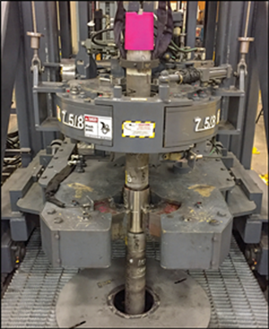
Reliable make-up. The specimens must first undergo make and breaks, Fig. 1. The test apparatus simulates vertical make-up of the connections on the rig floor and ensures the connection can be broken out and remade multiple times without damage or galling (friction adhesion between two sliding surfaces). The connections with the extreme interferences of the seal and threads are most at risk for galling and this is compounded by using the minimal recommended amount of thread compound and the maximum torques. Each specimen is made up and broken out twice with inspections for galling after each break out. It is then made up one final time to move onto to the next phase of testing.
Rotation while running and/or cementing and through bending. Fatigue is of concern to the production casing strings of shale wells and this is the biggest area where conventional connection testing methods are lacking. Fatigue is caused by cyclical loading and leads to progressive degradation of the metallurgical structure that can ultimately lead to small fissures in the grain structure of steel eventually leading to failure. Running pipe through the dogleg produces fatigue on each connection as it goes through the curve. This fatigue is compounded when combined with rotation to get the string to depth. While hard on the connection, it is a common practice onshore when drilled hole size is restricted by three string designs and loose formations are encountered that leave an irregular and unclean wellbore.
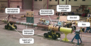
Additionally, operators are choosing to rotate the string while cementing with the hope of getting a more uniform cement job around the casing and wellbore. Rotation causes the entire string to oscillate within the wellbore and the connections are the most critical part of the string that will be most affected by fatigue. We achieve this effect in testing by applying a stress to a section of tubulars joined by the connection in the middle. The stress is achieved by a resonant fatigue machine, Fig. 2.
The amount of stress that is applied for the testing program causes up to a 25°/100-ft bend in the connection. This stress is induced in cycles, which cause a jump rope like effect on the specimen, with the connection being in the apex of the cycle just as oscillation of the string down hole would.
Some specimens are fatigued until failure (upwards of 20,000,000 cycles and lasting five days) to evaluate connection fatigue life and generate S-N curves. Other specimens are tested to real world fatigue life based on operator input and then go onto sealability testing to ensure the fatigued connection can still live up to its rated performances. These specimens will see up to 500,000 cycles before being stopped and inspected for integrity and sent onto the next phase of testing.
Thread compound degradation. The specimen is then subjected to extreme temperatures of up to 300°F for up to 24 hr. This is called the “bake out” step. This high temperature degrades the thread compound as it would over time and temperature in service. Thread compound quality is critical in semi-premium connections that have become increasingly popular. Semi-premium connections rely on sealing between the thread form to hold pressure rather than a metal-to-metal seal. With these connections, if the thread compound is not perfectly applied or has degraded over time, a leak path for internal and/or external pressure can be created. Bake out ensures this condition is tested in semi-premium connections.
Alternatively, for premium connections, we want to ensure that the metal-to-metal seal is being tested rather than using the thread form to assist with the sealability performance. This step also helps remove gases that form when the compound is heated up in subsequent testing phases. The gases will create bubbles in the thread compound and will be detected as false leaks later in the sealability portions of the testing.
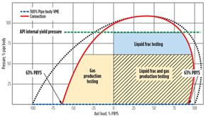
Stimulation of shale formations is what makes shale play completions unique. While most other oil producing areas have large reservoirs under very high pressure that can be volatile, shale oil is not under high pressure and it must be released out of the rock. Among other aspects, one of the driving factors into how fruitful the well will be is the size of the fracture into the shale rock. Higher pressures and large flowrates of fracture fluid are thought to generate the best returns. So, the internal pressure capability of the production casing tubulars and connection to withstand these loads is critical. Furthermore, this high pressure is experienced many times during fracturing the entire length of the lateral in stages. By applying and releasing these high internal pressures repeatedly, the steel tubulars are fatigued even further than they were during rotation while running and cementing.
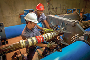
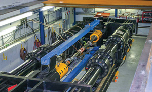
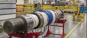
The company has designed a series of pressure tests that simulate this phase, Fig. 3. No other testing like it is available within the current standards. The testing applies up to 50 cycles of high internal pressure up to 100% of the connection’s rated minimum internal yield pressure. The internal pressure is held for 30 min. in each cycle while monitoring for leaks throughout the duration of the testing, Fig. 4. The pressure, created with water, is released and reduced after each cycle to simulate multiple fracture stages with fracture fluid. The analysis also captures axial loading due to effective tension produced by internal pressure in capped ended tubulars, which is what would be experienced in the production casing set downhole. The integrity of the material during this intensive fatiguing is monitored with multiple strain gauges placed at critical areas of the connection. These critical areas are being observed for deformation and overall hoop stress, which is known to increase with fatigue.
Production. After the fatigue and stress has been exacted on the specimens, the connections are tested to ensure they can withstand the production phase of the well for its life span. This phase is modeled after the API 5C5/ISO 13679 Series B test. The specimen moves through increasing internal pressure steps while applying varying axial and bending loads to the extremes of the connection’s limits. This is done in ambient temperature, then at 275°F while holding the connection up to a 30° bend, and then lastly in ambient temperature along with bending holds.
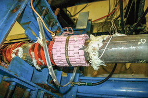
Considering few wells produce purely liquid condensates, these sealability tests are done with gas as the medium to ensure tightness of the metal seal. The bends are applied through rams that simultaneously put a flex and extension on the specimen while in the load frame, Fig. 5. Ceramic or induction heaters are used to elevate the temperature of the sample while it is undergoing sealability testing to simulate downhole thermal conditions, Fig. 6.
Technicians will typically finish the procedure with a limit load test that verifies the connection’s service envelope and expected failure mode. This is achieved by increasing pressure or axial loading until the specimen has a damaging failure.
OPTIMIZED SHALE CONNECTIONS
The testing protocol was used to develop the VAM SG connection, optimized for shale gas operations. It is an integral connection without a coupling to increase clearance between the wellbore and casing in tight three-string well designs. The metal-to-metal seal is positioned in the middle of the connection so that extreme bending and fatigue does not disengage the sealing mechanism. Its high-tension ratings make it one of the few integral connections that can be run top-to-bottom in a full-length production casing string.
The success of the testing protocol has enabled the company to produce an entire line of connections specifically suited for shale plays. They have options for extreme torque and 100% burst and collapse gas pressure ratings. The manufacturer has also taken its existing semi-premium product line and put it through the testing program. While no laboratory can reproduce the unpredictable nature of real-world drilling and completions, Vallourec’s testing program helps prove that its connections are designed to meet the requirements of a growing onshore market. ![]()
- Applying ultra-deep LWD resistivity technology successfully in a SAGD operation (May 2019)
- Adoption of wireless intelligent completions advances (May 2019)
- Majors double down as takeaway crunch eases (April 2019)
- What’s new in well logging and formation evaluation (April 2019)
- Qualification of a 20,000-psi subsea BOP: A collaborative approach (February 2019)
- ConocoPhillips’ Greg Leveille sees rapid trajectory of technical advancement continuing (February 2019)

