New frac-pack additive is step change in sulfide scale control for Permian long horizontals
The Permian basin, a sedimentary basin in West Texas and southeastern New Mexico, is one of the most prolific oil and gas basins in the United States, with total production over 14.9 Bbbl since 1993. The play spans approximately 250 mi wide and 300 mi long, and encompasses several sub-basins, including the Delaware and Midland basins.

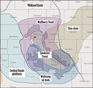
The geology of these basins is unique, as single wells can often source oil and gas production from multiple layers of formation rock across different geological zones. In this article, we are concerned with the Spraberry formation, which along with the Wolfcamp formation are regarded as the most productive oil-bearing zones in the U.S., and have been dubbed “Texarabia” by various press. The Permian basin comprises four major plays, including the Wolfcamp and Bone Spring horizontal plays in the Delaware basin, and the horizontal Wolfcamp and vertical Spraberry plays in the Midland basin. They routinely are drilled together, to access the stacked formations, Fig. 1.

HYDRAULIC FRACTURING/FLOWBACK FLUID MANAGEMENT
Hydraulic fracturing is an extraction technique used to facilitate enhanced oil and gas production from hydrocarbon-bearing formations. The process entails injecting hydraulic fracturing fluid downhole into an oil or gas well. The injection pressure used is sufficiently high to cause splitting/cracking of near-wellbore formation rock in the target, hydrocarbon-bearing formation, allowing release of stored hydrocarbon potential back to the wellbore via the artificially created fractures. Frac fluids used in these treatments routinely include solid proppant materials, such as graded sand, which pack into the newly formed fractures, and function to maintain fluid and gas transmission pathways from reservoir to wellbore, once the hydraulic pressure is released.
Fracing has contributed significantly to increased U.S. oil and gas production, by more than 50% of oil output and nearly 70% of gas production in 2015. This is projected to position the U.S. as the world production leader by 2021 (EIA 2015- https://www.eia.gov/todayinenergy/detail.php?id=25372). Hydraulic fracturing is regarded by most as the key enabling technology for economic production of unconventional resources, such as shales and tight sands.
This article addresses scale-related production challenges encountered during the initial 30-to-60-day hydraulic fracture treatment flowback phase in Spraberry long horizontal wells. During the initial post-shut-in flowback phase, the returning fracture treatment fluids dominate well-produced water ion composition (identified via chemical signatures of the fracturing cocktail components). The frac treatment progressively cycles out of the well with time, and eventually the well-produced water ion composition reverts to that of the reservoir waters.
In general, water processing/disposal costs during flowback treatment have been estimated to be between $1.00 to $8.00 per bbl of water (IHS 2016), and Permian operators typically include the first 30 to 60 days of flowback disposal into their capital costs per well. These costs can range from $0.3 MM to $1.2 MM, making up 5% to 19% of a well’s total cost (IHS 2014).
THE SCALE CHALLENGE: BLOCKAGES AND DEPOSITION
Typically, during flowback, approximately 30% to 75% of the fluid injected is returned in the first three weeks. It is, incidentally, a very interesting research area on chemical additives that enhance the return rates of these injected fluids, which can be achieved using surfactant chemistry or better polymer and breaker combinations. The return profile of slick water fracturing versus gel fracturing can be explained by this phenomenon in the Permian and many other plays in the U.S.
The very nature of fracing operations, with high pressures and large volumes of water, usually causes substances, such as released metals or dissolved salts from the formation, to be brought up with the flowback water, including trapped gases. Flowback water often contains high concentrations of total dissolved solids (TDS), heavy metals, suspended solids, sand and dissolved radioactive substances released from the formation (Zhang, 2014).
Hydraulic fracturing chemical additives make up less than 3% of the total frac fluids and are typically included to reduce well blockages, primarily from dissolved rock formation (calcium, magnesium, manganese and strontium). They also are used to limit heavy metal contamination (such as iron, chromium, copper, molybdenum, niobium, vanadium, and zinc) and formation fluid imbibition, as a result of leaching and mobilization of reactive surfaces exposed to the frac fluid. Chemical additives include scale inhibitors, corrosion inhibitors, iron control agent, pH and clay control agent, along with other additives, this typically guarantees a successful hydraulic fracturing job. World Oil previously published an article (July 2009, “Considerations for development of Marcellus shale gas”) that nicely shows the distribution of chemicals used for typical shale gas gel fractures, summarized in Fig. 2.
In some hydraulically fractured wells, scale deposition is not effectively controlled by the conventional scale inhibitor, either as a result of heavy metal and/or sulfide poisoning, leading to severe scale deposition in the recently opened fractures and wellbore. Flowback duration and production are immediately impacted by these depositions, and well re-entries with an associated well cleaning plan are required to reinstate production.
In this article, the challenges that a Permian operator faces during completion of several 50-stage, hydraulically fractured wells are highlighted. It was discovered that these failures were attributed to iron sulfide (FexSy) and zinc sulfide (ZnS) scale deposition during flowback. Further, this article introduces the industry’s first, innovative solution to control these types of exotic scale effectively during fracturing and flowback.
The operator tried different mitigation options, including increasing concentration and changing out the standard scale inhibitor, among many, all of which were unsuccessful in preventing well failures. As the cost accumulated in well re-entries and associated mitigation options, a request was sent to Clariant Oil Services to provide an effective, lasting solution.
The development of the chemistry has been covered adequately in previous publications (Savin, et al. 2014; Wylde, et al. 2015). Readers are encouraged to check further into the unique characteristics exhibited by this patented chemistry for dispersing and inhibiting sulfide scales, in comparison to traditional scale inhibitor products’ inhibition mechanisms.
FIELD SOLUTION AND DEPLOYMENT
For the field case history presented here, both the capital expenses per well and the number of well re-entries for scale mitigation increased. Several remediation chemistries were eventually trialed, which provided only temporary relief from the continuous sulfide scaling experienced in the wellbore and across ESPs (electrical submersible pumps).
The operator requested a solution—to control iron and zinc sulfide—to be delivered during the hydraulic fracturing operation. Key performance indicators (KPIs) were developed between the operator and the service company, to align on pass/fail criteria in the laboratory and field. These KPIs included the following:
- Exceptional performance to inhibit iron and zinc sulfide
- Compatible with frac fluid (pad–acid and non-acid pads)
- Suitable adsorption and desorption characteristics (squeezable)
- Temperature and high-pressure (shear) stability
- Zero increase in H2S evolution during flowback.
The chemistry used, as described above, was proven in the detailed testing protocols to be a viable sulfide inhibitor for this hydraulic fracturing application. The use rate was recommended at an applied dose rate of 1 gallon per thousand (GPT) in the pad and 0.4 GPT for the remainder of the 50 stages. Compatibility tests and subsurface performance tests were carried out prior to the field application, showing excellent compatibility with the frac fluids and a favorable adsorption–desorption (isotherm), and therefore an assumed field squeeze performance, Fig. 3.

DEPLOYMENT RESULTS
The sulfide scale inhibitor additive used in the hydraulic fracturing treatment resulted in control of all sulfide scale issues downhole in the target wells. Well scaling health was determined via zero fouling, combined with monitoring of well-produced waters, which showed steady and consistent dissolved iron and zinc concentrations. There was no increase in H2S evolution during flowback. It was not possible to determine the residual scale inhibitor concentration, due to the presence of high levels of interfering chemical species in the flowback fluid. The primary culprit is believed to be the generic drag reducer chemical additive employed throughout the treatment.
ESP run-times increased from a few weeks to several months of continuous operation, with motor temperature indicators and across-pump differential pressure transducers indicating low or no scale development. In addition, several ESP units were recovered for inspection topsides, where no new significant sulfide scale deposition was identified within any unit.
For wells equipped with pressure transducers downhole, it was deduced that wellbore tubing was free from any new, significant solids deposition.
The laboratory tests showed, and it was corroborated in the field, that the new sulfide scale inhibitor technology reduced the iron and zinc scale deposition rate to 99.9% (compared to the previous untreated water), and met the KPIs set for performance. The technology proved to be an excellent sulfide inhibitor, acid and non-acid, frac pad-compatible, squeezable, and temperature-and-high-shear-stable.
CONCLUSION
The new-generation sulfide scale control additive dosed into the frac treatment package was very effective at controlling various types of sulfide scales during the post-frac treatment production phase. As a direct consequence of deploying the additive, the Permian basin operator gained the following:
- Economic benefit, with respect to continued production and reduced downtime/deferred oil cost
- Economic benefit via savings made on well re-entry frequency and remedial cleanup actions
- Reduced concerns of H2S evolution during flowback and provided environmental and cost-savings benefits.

REFERENCES
- EIA, 2015: “https://www.eia.gov/todayinenergy/detail.php?id=25372”
- EIA, 2016: “Trends in U.S. Oil and Natural Gas Upstream Costs,” March 2016.
- Crédit Agricole, CIB Report 2016: “Oil & Gas Productivity Gains and Their Impact on Energy Prices and Trade Flows in North America,” 2016.
- Zhang, T; K. Gregory; R. W. Hammack; and R. D. Vidic, RD- 2014 “Co-precipitation of radium with barium and strontium sulfate, and its impact on the fate of radium during treatment of produced water from unconventional gas extraction.”
- Savin, A., B. Adamson; J. J. Wylde; T. Trellenkamp; C. Kayser; J. Kerr; and C. Okocha, “Sulfide scale control: A high efficacy breakthrough using an innovative class of polymeric inhibitors,” SPE paper 169777, SPE Oilfield Scale Conference and Exhibition, Aberdeen, UK, May 14–15, 2014.
- Wylde, J.J.; C. Okocha; M. Bluth; A. Savin; and B. Adamson, “Iron sulfide inhibition: Field application of an innovative polymeric chemical,” SPE paper 173730-MS, SPE International Symposium on Oilfield Chemistry, April 13-15, 2015, The Woodlands, Texas.
- Todd, M.; C. Strachan; G. Moir; and J. Goulding; “Process for inhibition of sulfide scales,” World Oil, 2013/152832 (2013).
- Arthur, J. D.; B. Bohm; and M. Layne, “Considerations for development of Marcellus shale gas,” World Oil, July 2009.
- Shale technology: Bayesian variable pressure decline-curve analysis for shale gas wells (March 2024)
- What's new in production (February 2024)
- U.S. operators reduce activity as crude prices plunge (February 2024)
- U.S. producing gas wells increase despite low prices (February 2024)
- U.S. drilling: More of the same expected (February 2024)
- U.S. oil and natural gas production hits record highs (February 2024)
- Applying ultra-deep LWD resistivity technology successfully in a SAGD operation (May 2019)
- Adoption of wireless intelligent completions advances (May 2019)
- Majors double down as takeaway crunch eases (April 2019)
- What’s new in well logging and formation evaluation (April 2019)
- Qualification of a 20,000-psi subsea BOP: A collaborative approach (February 2019)
- ConocoPhillips’ Greg Leveille sees rapid trajectory of technical advancement continuing (February 2019)


