Hydraulically powered beam gas compressor fulfills multiple roles
Permian Production Equipment, Inc. (PPEI), a Texas company, was formed by Charlie McCoy in the early 1980s. While working and visiting with some operators in the Permian basin area, we recognized the need for better gas and vapor compression, as well as a simple system of stand-alone Vapor Recovery Unit. This was due to the need to improve gas compression to make casinghead gas available for sale, to satisfy stricter environmental regulations and standards, and still be able to work in hazardous and corrosive applications under all weather conditions throughout the oil patch. We studied this need and developed the answer. This is when we took the Beam Gas Compressor (BGC) and integrated it with its own prime mover.
HISTORY OF BGC DEVELOPMENT
One of the inventions was the BGC. I (Charlie) was doing some artificial lift with a company in the Sand Hills, south of Odessa, Texas, when we drove by one of the wells that had the casing open. It was blowing gas laced with H2S to the atmosphere, out through the sand dunes, to relieve “gas locking” or gas interference in the downhole pump (DHP). Lying in the middle of the gas stream were a number of dead quails. I thought this was unacceptable to the environment and wildlife.
Later that day, I came back to this well and watched the pumping unit lifting the rods with the horse head and walking beam going up and down. In the process, I came up with the idea of using a cylinder, which is now called the BGC, to draw gas and pressure from the casing, using energy from the pumping unit. This became the first well to utilize the BGC, to relieve back pressure on the formation, allowing additional fluid flow from the formation to the wellbore and reducing gas interference in the DHP. The operator subsequently experienced an increase in oil production, as well as gas sales. The company subsequently implemented more BGC applications in this field, as well as in other fields that it was operating. This was the beginning.
HYDRAULIC BEAM GAS COMPRESSOR (HYBGC) DEVELOPMENT
Operators utilizing the BGC would tell us, over the years, that they wished there was some way to use the device when there was no pumping unit available, and some wanted to utilize the simple system of compression in other applications. So, about three years ago, we took a BGC down from the pumping unit and incorporated a hydraulic ram to drive the BGC in a double-acting mode. It is the same simple system of compression that has been in use for almost four decades. With a simple hydraulic power unit, we now enjoy the simplicity of the BGC to compress casinghead gas, boosting gas in the field to the sales line (Fig. 1) or to compressor stations, as well as utilizing it for vapor recovery units (VRUs).
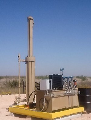
Basic HyBGC operation. The HyBGC does not require a pumping unit to compress gas. The HyBGC is a stand-alone unit and can be utilized in several gas compressor applications. The HyBGC uses hydraulic oil pressure as its prime mover to drive the HyBGC’s reliable, double-acting, single-stage, reciprocating gas compressor cylinder that has been the trademark of the time-tested BGC. The hydraulic oil pressure is provided through a hydraulic piston and cylinder arrangement that is mounted to the top of a gas piston and cylinder. Through it, the hydraulic forces are transmitted to the gas cylinder through a common rod between cylinders, as it extends all the way into the gas cylinder and to the gas compression piston. The compressor works in “double-acting” fashion where, with each piston direction, gas is simultaneously being compressed on one side of the piston and being drawn into the other side. The piston is reversed at the end of each stroke, which causes the compression and intake side of the piston to be reversed. When done in a continuous fashion, this makes a reciprocating motion.
To drive the piston’s reciprocation back and forth, hydraulic oil flow is applied in reversing directions to the hydraulic piston. When the gas piston reaches the end of the compression stroke, the piston locator signals the system to reverse directions, and the hydraulic flow is then reversed to the hydraulic piston to start the piston moving in the other direction, and continues to reverse after the gas piston reaches the end of its travel in the opposite direction. The mechanism that tells the hydraulic system flow to reverse is simple proximity switches mounted on the gas cylinder. The sensors are located at each end of the compression cylinder. The flow reversal is accomplished through a standard hydraulic shuttle valve that reverses the pump flow destination from one direction to the other. The HyBGC can be powered electrically or, when electricity is not available in remote locations, it can be powered by a natural gas engine.
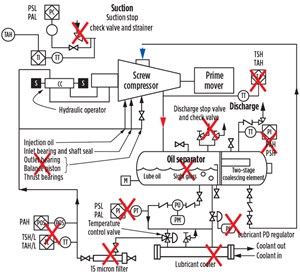
The HyBGC can be controlled by different methods. It can be controlled by a simple start-and-stop, based on suction pressure. The HyBGC is usually installed with a simple bypass that controls the source pressure, allowing continuous run time of the system. Variable speed drives may be incorporated to speed up and slow down the compression cycles, to compensate for variations in gas flow to the system. Telemetry is available from the operator to control the system via Internet. With the HyBGC, the flow of hydraulic fluid to the system can be adjusted to regulate the strokes per minute of the system, thereby speeding up or slowing down the compression cycles to regulate the gas volume required to be compressed.
Advantages. The HyBGC offers up to 10 ratios of compression versus three to five for standard reciprocating systems. The large cylinder and slow speed allow much more heat to be dissipated over every stroke. This greater compression ratio allows the HyBGC to deliver gas into a wider range of pipeline pressures without having to have multiple-stage compression.
To control the flow, source pressures, and volume of compressed gas, the first option is to open a small needle valve in the hydraulic system that bypasses the oil to the reservoir and thereby slows the strokes per minute. The second option is the piston proximity of sensors that can be moved closer together, to shorten the stroke of the unit.
In the case of liquid ingestion, moving liquids out of the gas cylinder compression is automatically adjusted in travel, until the liquids are cleared and pushed downline into the production equipment for separation. Wet gas and liquid slugs do not harm the HyBGC, thereby eliminating the need for scrubbers and return pumps, Fig. 2.
The maximum hydraulic pressure allowed to the system can be adjusted, so no damage to the system can occur. It can be set below the relief valve setting to eliminate gas discharge to the atmosphere, making the system environmentally friendly.
The gas cylinder piston seals are positive seals, causing the system to become a pump. The slow-moving piston allows the compression chamber to be filled completely with gas before it changes direction. This feature makes the HyBGC a more efficient compression system. The compression cylinder is made of material that does not require lubrication. It is a totally enclosed compression system, so there is little possibility of any gas being released to the atmosphere, complying with Quad OOOO federal regulations.
The compression cylinder and all of its components are designed to be corrosion-resistant and can be utilized in H2S and CO2 environments without concern. The HyBGC can be designed to compress high-temperature gas and/or be utilized in steamfloods. With simplicity of components, the HyBGC can be repaired easily by most field personnel.
APPLICATIONS: VERTICAL AND HORIZONTAL WELLS
Rod pumping systems. Operators are utilizing the HyBGC to relieve casinghead pressure, to reduce back pressure on the formation, allowing additional fluid flow to the bore from the formation. Depending on the Productivity Index for the formation, this increased production allows operators to receive additional revenue from existing wells. Also, when gas is drawn out of the casing via the HyBGC, and the pressure is reduced at the face of the formation, the gas breaks out of solution and moves up the casing and away from the Lift system. This reduces gas interference in the downhole lift system and eliminates fluid found in rod pumping systems.
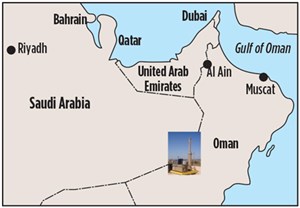
ESP and PCP lift systems. One of the main causes of failures in ESP and PCP lift systems is gas and/or gas slugs entering the pump. By reducing the pressure in the casing, the gas will accelerate breaking out of solution and is then drawn from the well by way of the casing. The ESP and PCP lift systems are designed to pump fluid, not gas. This reduced pressure and gas removal from the casing will allow the ESP to concentrate more on the fluid removal from the bore, without having to deal with the excessive gas entrained in the fluid. The value of using the HyBGC with an ESP was demonstrated in an application with a Middle Eastern operator, Fig. 3.
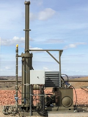
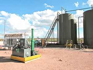
Vapor Recovery Unit. The HyBGC can be designed specifically to move vapors from stock and storage tanks. It is designed to move the high-BTU gas that is prevalent in this application. The HyBGC also can deal with the H2S associated with tank vapors. In applications over the past three years, there has been a 99.4% run time, Fig. 4. In addition, the HyBGC’s mettle was proven in a North Dakota case study. Installed in December 2015, in high H2S service, in a cold environment, the unit has functioned for more than 2.3 million cycles with not a single service call, Fig. 5. So, the HyBGC has proven to be a most reliable system of compression for vapor recovery.
Gas line booster. The HyBGC also is being used to gather field gas from a common line to boost the pressure to feed larger field compression stations. Where gas is gathered from long flowlines that have undulating properties—because of the uneven terrain—pockets of fluid will accumulate and then, at some point, advance to the HyBGC. The HyBGC can handle these slugs of fluid without any adverse effects on the system. The fluid is simply pumped down the line to the production equipment, to be separated.
CONCLUSION
The Hydraulic Beam Gas Compressor is relatively new to the industry, with three years in production, but for all intent and purposes, the technology has been around for decades. The double-acting BGC has been in service to the industry since the late 1970s in oil fields worldwide. Operators consider the combination of these two reliable processes to be an innovation, and one that has added new options for gas and vapor compression to a centuries-old industry. ![]()


