What’s new in artificial lift?, Part 2
Continuing last month’s “What’s new in artificial lift?” discussion, we report on several items that we hope you find useful.
ESP DEVELOPMENTS
An electric submersible pump (ESP) downhole assembly will typically include the ESP pump, a gas handler/separator or standard intake, a seal section, a submersible motor with a connected power cable that runs to the surface, and often a downhole sensor package that communicates pump and wellbore performance information back to a surface interface system. The surface equipment may include a variable speed drive (VSD) or switchboard, a motor protection system and/or an intelligent control system designed for applications that require advanced system control and monitoring.
Estimation of an ESP’s electrical performance is conducted at the surface, within the VSD, using a selection of electrical and mechanical parameters. It is rare that any real-time instrumentation is installed at the output transformer or on the motor side. Hence, motor performance, losses, real harmonics and changes in the system are not measured directly.
This lack of accurate measurement can have a negative impact on operations. In many cases, it can lead inevitably to production loss, cost increases and permanent damage to the lifting equipment.
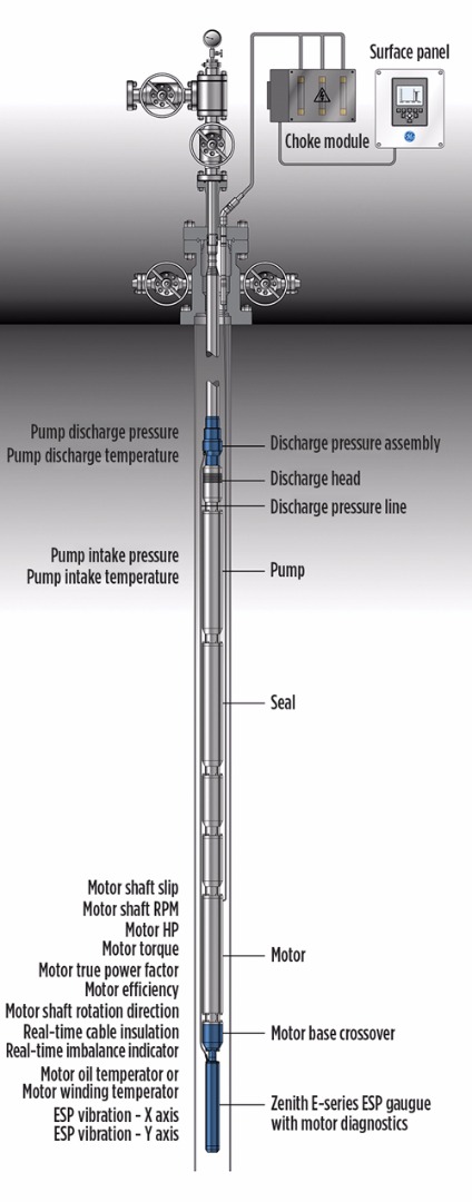
ESP gauge with motor diagnostics. GE Oil & Gas has been working to identify the root cause of continuous failures and production loss, and establish the essential measurements needed to effectively boost production and improve artificial lift performance. Despite an increase in smart well solutions and industry expertise, operators advised that many important decisions are still being made—whether by the smart solutions or the operators themselves—based upon calculated parameters or following laborious data analysis.
While continuing to deliver real-time reservoir and pump system measurements, GE’s Zenith E-series ESP gauge with motor diagnostics (Fig. 1) has been developed to provide essential real-time motor measurements, ensuring that operational decision-making is based on true and accurate measurements, minimizing equipment failures and reinforcing production optimization efforts.
GE’s motor diagnostic development group considered any impactful changes to familiar products and processes resulting from the new gauge design, avoiding any significant extra cost or special requirements, and any new design or installation requirements for ESP teams.
Conventional pump pressure and temperature measurements are communicated to surface via the ESP cable, along with insightful mechanical and electrical motor measurements, ruling out any empirical trials, minimizing production loss by maximizing equipment run-life, ensuring the motor remains running at its frequency/load sweet-point, and enabling effective cost control.
GE’s solution has been designed not only to provide true measurements, helping ESP operators make decisions confidently, but to also unlock increased control of the ESP system by providing experts and smart solution systems with direct, accurate measurements from which accurate derivatives can be made. The diagnostic gauge measures a holistic set of pump and motor parameters.
The system helps eliminate electrical failure while focusing on the cost of energy by monitoring the true power factor, motor efficiency and system insulation. In parallel, operators receive key parameters essential to the prevention of mechanical failures, such as torque, slip and RPM. This enables operators to maximize production by using the best, and most efficient motor/power performance.
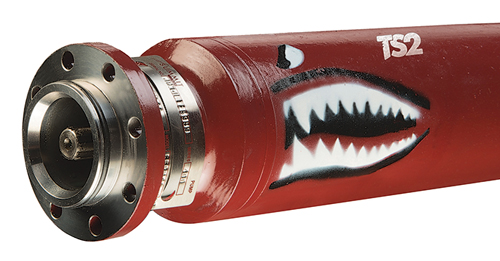
Summit introduces new products. Summit ESP has introduced its durable, Tiger Shark 2 (TS2) pump, Fig. 2. The TS2 is designed to address the gassy, abrasive and high-temperature conditions found in many unconventional reservoirs by incorporating enhanced head/top bearings and wear-resistant bearing material for supplemental pump shaft support.
The TS2 also incorporates bushings with a high thermal expansion material (HTEM) ring, providing a secondary mechanical lock between the bushing and diffuser to improve run life in cycling gas and HT applications. The increased wear resistance on the bearing and bushing improvements, used in conjunction with Summit’s XRange mixed flow stages, and the patented Erosion Buster pump diffusers, have proved to produce up to a three-fold increase in pump performance.
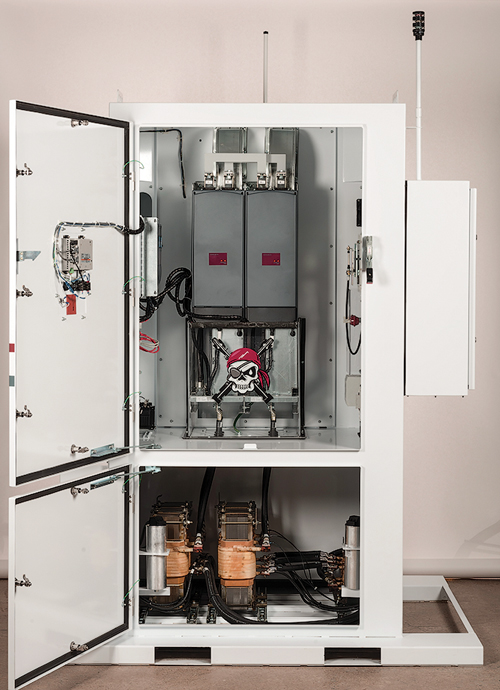
Earlier in the year, Summit introduced the Adaptive Control System, ACS-15 VSD (Fig. 3) with active front-end harmonic cancellation capabilities reducing the vibrations reflected into the power grid. Later this year, Summit plans to introduce higher-temperature motor lead extensions and higher-efficiency motors.
Summit complements pump-related product offerings with 24/7/365 services through monitoring and localized application engineering support, and on-site field technicians.
New technology improves runlife of ESPs. A root cause failure analysis uncovered new facts about ESP system failures. The study determined that electrical failures can be attributed to high-frequency line-to-ground (L-G) anomalies created from the inverter of the VSD. In some instances, mechanical failures have been diagnosed as electrically induced high-frequency events. An investigation into this failure mode showed that no L-G filtering existed in the ESP industry.
Although recommendations to reduce the damaging effects of these abnormalities are provided by the U.S. DOE, they are only possible for surface systems; not downhole ESP systems. The only solution for these applications is to mitigate those high-frequency components, and common mode currents, on the surface.
High-frequency noise on an ESP system operating with a VSD can cause a host of power quality-related anomalies, including nuisance tripping, instantaneous overcurrent, zero crossing faults and erratic data transfer. High-frequency currents also cause skin effect heating, and high-frequency voltages cause reflection. The weakest links in the system are penetrators, splices, motor lead extension/pothead, motor windings and bearings. All are susceptible to premature failures.
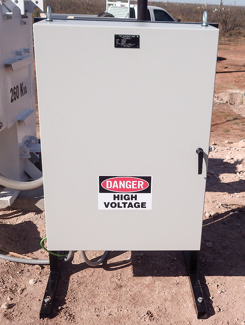
To solve these issues, Magney Grande has introduced its Guardian line of common-mode filters (CMF), a standalone component that extends overall run times by reducing high-frequency-induced failures, Fig. 4. At the typical VSD switching frequency of 2,000 Hz to 2,400 Hz, the insulation is rated for 0.03 amps. Less than one amp of high-frequency current discharging across bearings can cause mechanical failures.
The CMF is applied at the medium-voltage (MV) taps of the step-up transformer, or at the output of a MV VSD. The CMF shunts the damaging high-frequency currents to ground at the surface, dissipating skin effect heating from traveling downhole and putting stress on the entire system. It effectively mitigates the damaging currents and reduces the high-frequency reflection caused by long cable lengths. The Guardian CMF is a cost-effective addition to all filtered PWM VSDs in the ESP industry.
Rig-less ESP system. Conventionally replacing ESPs to accommodate downhole changes or restore failed components requires rig or hoist interventions that cause production deferment and increased costs. The operation also increases HSE risks associated with complex well interventions.
The Schlumberger ZEiTECS Shuttle (Fig. 5) rigless ESP replacement system features a downhole electrical wet-connector that enables standard ESPs to be transported through tubing on wireline, coiled tubing or sucker rods and plugged into a downhole docking station—all without a rig or hoist. The rigless ESP replacement system minimizes production deferment, reduces operating costs, and HSE risks, while maximizing ESP run life by facilitating regular preventative maintenance. The shuttle also enables operators to exchange ESPs in response to changing well conditions instead of waiting for a failure.
The system has two principal assemblies: 1) the rig-deployed semi-permanent components, including a docking station; and 2) the riglessly retrievable components, including a standard ESP with a motor connector on the bottom and a slip-lock seal assembly on the top.
The docking station is deployed on the bottom of jointed tubing with cable clamped or banded to the outside and houses three electrical wet connectors (receptacles) to supply power to the standard, three-phase, AC, induction or permanent magnet motor. The docking station also has a facility to engage and rotate the motor connector, so that the wet connectors align, and a landing surface to bear the weight of the retrievable string and the reactive forces generated by the ESP. An offset through-bore allows reservoir access beneath.
The motor connector is deployed at the base of the retrievable string. The connector has three electrical wet plugs and an alignment spear that automatically aligns the connectors with those of the docking station.
Shuttle systems have been deployed successfully both on- and offshore around the world. This field-proven technology increases production uptimes and drastically reduces well lifecycle cost.
BHI’s rig-less deployed ESP system. The Baker Hughes TransCoil rigless deployed, coiled tubing ESP system—developed in partnership with Saudi Aramco—eliminates the need for a rig in fields where availability is a concern, or where high intervention costs limit artificial lift options, Fig 6. The system features an inverted ESP, with the motor connected directly to a new-type power cable configuration. This eliminates the traditional ESP power cable-to-motor connection, which improves overall system reliability. Unlike wireline-deployed ESPs, the fully retrievable ESP does not have an in-well “wet connection,” which requires a rig to pull and replace it, if the connection fails.
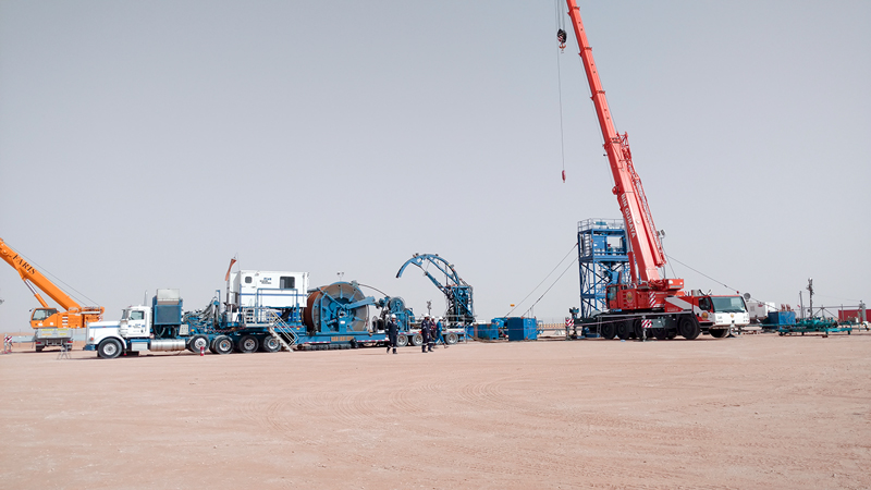
The system’s unique cable design extends the operating range to 12,000 ft. This compares favorably to traditional CT-deployed ESPs, which are limited to approximately 7,000 ft because, at greater depths, the weight of the power cable will cause it to collapse inside the CT, creating an electrical failure. The system can be installed in 4½-in. to 9-in. casing, in wells with flowrates up to 18,000 bpd. In mature offshore fields, where high intervention costs can limit the application of ESPs, the system can be deployed through the existing 4½-in. tubing, saving the time required to pull an existing completion.
Another advantage of the technology, compared to wireline-deployed ESPs, is that it can be installed through a deviation in the wellbore. This capability allows operators to land the ESP closer to the producing zone for greater reservoir pressure drawdown and reserve recovery.
In Khurais field, Saudi Aramco was looking for an alternative deployment method to reduce downtime and costs. The yearly rig schedule for the field made it difficult to arrange unplanned workovers, creating long lead times to retrieve and install the ESP system.
To solve the problem, the operator and service provider collaborated to develop a tool that would eliminate the rig, and address harsh downhole conditions. On its first installation, including the mobilization time of a CT unit, the JV TransCoil system successfully returned 8,000 bpd to production after a year of downtime. The rigless deployment reduced ESP installation time by 50%, compared to a rig-deployed system, and workover costs by more than 50%.
PCP DEVELOPMENTS
Depleted wells have a tendency to produce gas, which can cause problems on artificial lifting systems. ESPs often have difficulty handling wide and varying flows. Even progressing cavity pumps (PCP), which do not have the gas lock issues that plague ESPs, can be affected when the free gas at the intake pressure exceeds 20%. In wells with a high dogleg severity, the chance of equipment failure is even greater for rod-driven PCPs.
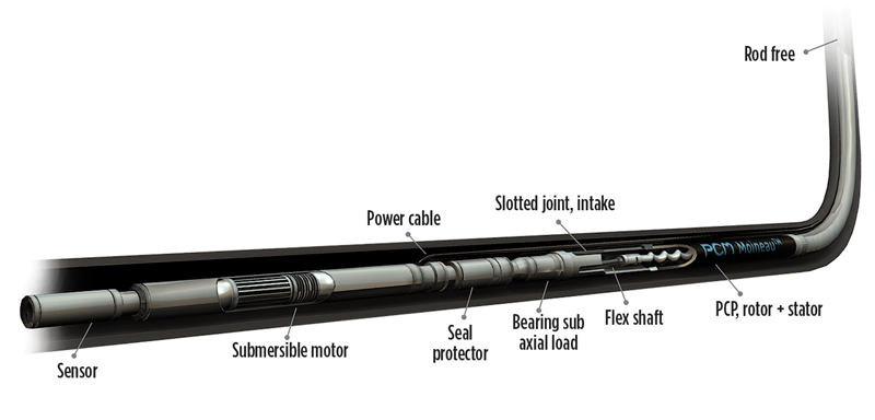
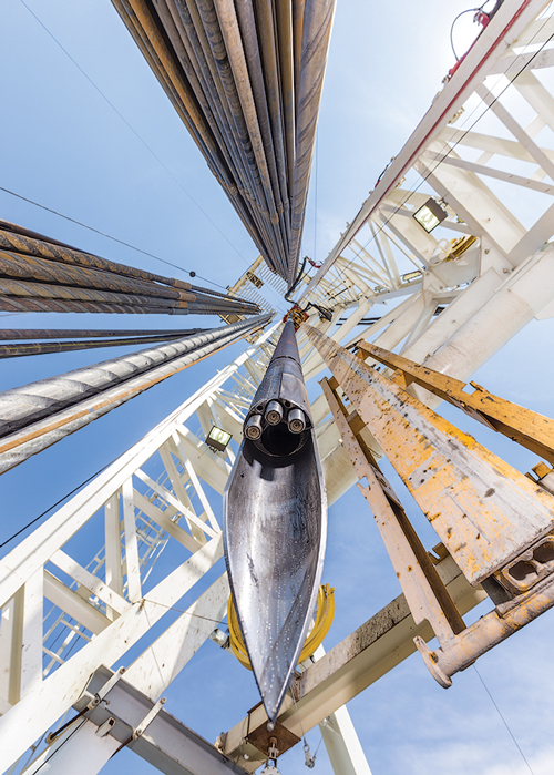
Combining two breakthrough technologies for difficult wells. PCM has created a highly-efficient electrical submersible PCP for difficult wells. The system contains two technologies, including a hydraulically regulated PCP (HRPCP) for high GOR wells, which is coupled with a permanent magnet motor (PMM), Fig. 7.
Associating a submersible permanent magnet motor with a submersible PCP creates a single artificial lift system that incorporates the benefits of a PCP pump with the advantages of an ESP-type completion. The rod-less system eliminates rod failure, tubing punctures or space-out issues associated with a traditional rod-driven PCP, especially in highly deviated wells. It also helps to reduce tubing losses generated by the initial rod string and avoid unnecessary energy losses from a surface drivehead. This advanced alternative PCP system outperforms ESPs, which can gas lock and suffer from premature failure, due to sand wear.
Since it is derived from PCP technology, the HRPCP is better equipped to handle sand, solids and viscous oil without issues. Its unique rotor is designed for better pressure distribution inside the pump. PCM patented hydraulic regulators are embedded in the rotor, providing equally distributed pressure gradient and temperature gradient along the rotor. Pump reliability and run life are improved significantly. As a result, even with erratic multiphase flow patterns, the HRPCP can maintain a very stable and smooth operating behavior, along with high run life, even in extremely high GVF environments.
Finally, switching from a traditional induction ESP motor to a PMM eliminates the need for an expensive, unreliable gearbox in the BHA, increasing system efficiency while reducing power consumption.
The system has been deployed successfully in the Middle East for lifting 17°API heavy crude. The pilot was installed with the pump settled at 83º in a highly deviated well that was experiencing excessive PCP failures. The system passed through a 14°/100 ft deviation with setting 1,010 ft depth. It has been running for two years without production disruptions, or decline, despite a high gas content.
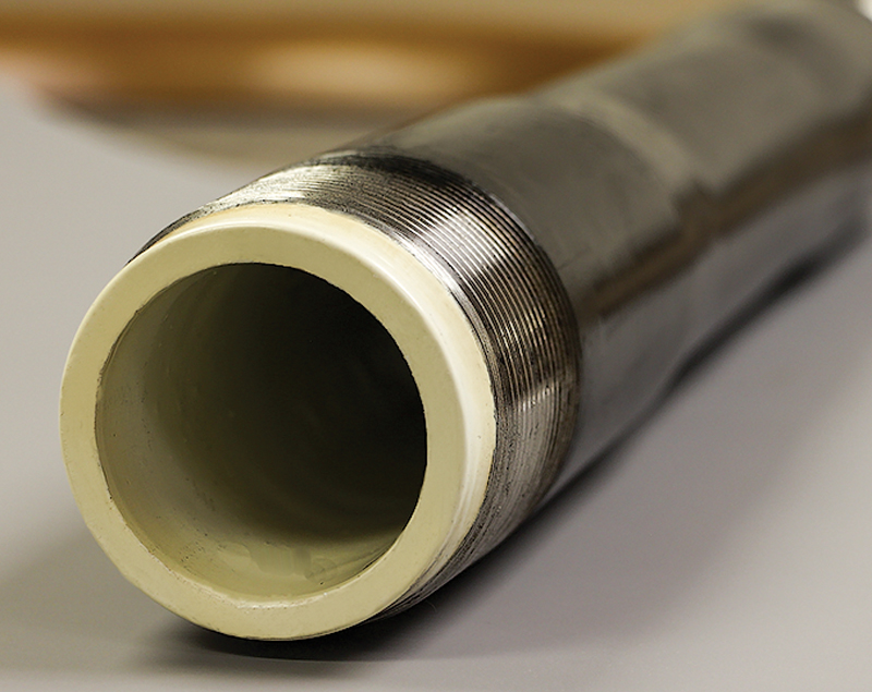
Liner extends mean time between failures. Lightning Rod and Pipe is offering a lined tubing technology that reduces the meantime between failures in PCP and rod pumping applications. LightningFlo LF115 (Fig. 8) uses a unique polymer that lowers frictional wear from rod movement, resists corrosion-causing chemicals and can maintain integrity in high-temperature operations.
The tubing’s high-performance resin addresses the limitations of early offerings at a lower cost. The new resin works well in high temperatures, is more resistant to corrosion, has lower coefficients of friction, and stands up to abrasive wear.
LightningFlo LF115 lined tubing uses raised temperature polyolefin ketone (POK). It is now being extruded into thermoplastic tubing liners at a much lower price than other high-performance resins. POK was originally commercialized by Shell Chemical as a replacement for HDPE in offshore applications, where higher performance was needed. POK polymers have few known solvents and are particularly resistant to salt solutions, hydrocarbons and most other chemicals present in oilfield applications.
Thermoplastic liners tend to collapse when pressure is reduced abruptly inside the liner in the presence of an annular pressure. This can occur in oil wells when the tubing is pressured up and bled off rapidly. The tendency to collapse is much greater, if the permeability of the liner is high. Laboratory testing shows that a 5-in. pipe lined with POK has twice the collapse strength at room temperature than a pipe with HDPE liner.
Additionally, successful laboratory tests have validated the specifications of the liners. Multi-component crude exposure testing was done over an eight-month time period over a temperature range from 68°F to 176°F. The modulus, yield stress and elongation properties were relatively unchanged after this test. A separate eight-month test exposed POK to a fluid from a North Sea sour gas environment at 221°F. Tensile properties stabilized after two days of exposure and remained relatively unchanged for the remainder of the testing period. The POK liners have been proven to extend the mean time between failures in well installations in multiple locations over the last year.
PLUNGER LIFT DEVELOPMENTS
Plunger lift is used commonly to remove liquids from gas wells or produce relatively low volumes in high-GOR oil wells. Because the plunger provides a “seal” between the liquid and the gas, a well’s energy can be used to lift liquids out of the wellbore efficiently.
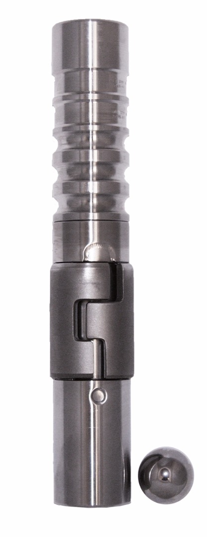
Pad sleeve bypass plunger. A pad sleeve bypass plunger (Fig. 9), by PCS Ferguson (part of the Dover Artificial Lift group) reduces shut-in times and maximizes production. This plunger is the first of its type on the market, making more trips with faster fall times. It often helps wells achieve a significant increase in daily production. This padded version has more controlled travel times than the traditional sleeve and allows for a tighter seal in wells with tubing irregularities.
The ball and sleeve are held in the lubricator by the separator rod and latch. When the latch opens, the combination of the differential pressure and the rod hold the sleeve, while the ball falls toward the bottom of the well. When the differential pressure decreases, the sleeve begins to follow.
When the sleeve reaches the bottomhole bumper spring, it joins the ball and forms a seal. Pressure builds, causing the ball and sleeve to travel together while lifting fluid to the surface. When the plunger reaches the lubricator, the separator rod extends through the sleeve, knocking the ball down the tubing and the cycle repeats.
A well in Bridgeport, Texas, was producing 5 bopd and 500 Mcfgd, using a traditional 9-in. sleeve and a stainless steel ball. The well is 6,760 ft deep and has slight tubing irregularities.
The traditional sleeve plunger was replaced with a pad sleeve bypass plunger. After three months, the new plunger traveled 4,735 round trips, running at 11.5 min/trip. The plunger increased oil production 40% and gas production 10%.
GAS LIFT DEVELOPMENTS
Gas lift involves injecting gas through a well’s tubing-casing annulus. Injected gas aerates the fluid to reduce its density; the formation pressure is then able to lift the fluid column and force it up the wellbore. Depending on the nature of the well’s production and the characteristics of the lifting equipment, gas may be injected continuously or intermittently.
Improved gas lift for liquids-rich wells. Gas-lift is gaining popularity in oil shale wells. However, the design of gas-lift compressors is virtually the same as that used for gas sales, even though the two processes have different requirements.
This standard design is physically capable of performing either task, but the overriding focus of the present design is to prevent gas from overheating. With gas-lift, the focus should, instead, be on preventing the gas from being too cold. The focus on preventing high temperatures resulted from downstream equipment that functioned poorly above 100°F, and often gas sales contractual temperature limitations are 130°F or lower.
Design components favorable to “gas sales” work against the successful operation of a gas-lift compressor, because NGLs have not been removed, due to the lack of an on-site gas plant. When these liquids go through the compression cycle, they often condense in the gas coolers. This causes problems in the compression process, and results in additional expense, potential downtime and environmentally unfriendly practices.
Two prevalent operating problems caused by hydrocarbon condensation in a gas cooler are freezing dump lines, and hydrate formation plugging of components. In a frozen dump line, components such as propane, are in a liquid phase at 150 psig and typical first inter-stage pressure ranges. When dumped to a tank operating at atmospheric pressure, the propane will vaporize, extracting the heat of vaporization from the surrounding environment.
Propane has long been used as a refrigerant because of the significant cooling that is achieved when this happens. A secondary issue is the vapor cloud being introduced into the tank, and whether tank vapor recovery is designed to handle this. The end result can be a significant recycle (or recirculation) of propane, greatly reducing the efficiency of the gas-lift compression system.
Continuous methanol injection is used to combat the problems of hydrate formation and dump line freezing. However, the practice of pumping methanol, besides being expensive, is also somewhat dangerous, as methanol burns without a visible flame. As widespread use of methanol expands with the shale plays, this safety consideration should not be ignored.
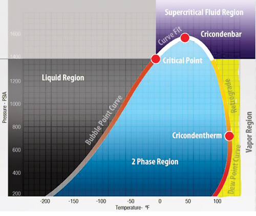
According to Encline Lift, an alternate method for solving these two problems is to prevent them from occurring in the first place. This is done by designing the gas cooling system to keep temperatures in the vapor region (yellow) of the phase diagram (Fig. 10), where hydrocarbon condensation will never occur. For gas-lifted wells with paraffin issues (exacerbated by lean gas injection), leaving the final outlet temperature above 150°F may suppress paraffin formation in the upper portion of the tubing string.
POWER, AUTOMATION, CONTROL AND MONITORING
McKinsey statistics show that engineers spend around 28% of their working days dealing with email, while Industry Week says 25% to 50% of their time is spent in meetings. That’s why it’s important that well analysis is automatic, providing engineers with ranked opportunities and problems.
Monitoring is critical. Although most wells have downhole sensors and real-time surface data, all too often the information is not actually used to optimize production. What’s even more problematic, is the use of different vendor-provided monitoring systems for ESP and gas lift wells can cause data to be scattered over multiple systems. This makes comprehensive analysis difficult, and wells are run sub-optimally. These issues, combined with WTI hovering around $45 to $55/bbl, require that wells on lift be fully optimized, 24/7.
CO2 modeling and gas lift analysis. Artificial Lift Performance’s (ALP) Pump Checker is designed to solve a multitude of these issues. The system brings all data together, regardless of whether an ESP or gas lift is being employed. APL’s Pump Checker also has two new functions:
- Simulation of CO2 phase behavior through ESPs for CO2 floods
- Gas lift analysis.
Pump Checker provides a simple, one-world view of all the pumps and systems that an operator uses. It enables engineers to react more quickly to opportunities and alerts them to unforeseen problems. The technology means more oil and fewer failures. The Pump Checker:
- Integrates real-time and production data on a single platform.
- Gives the same data presentation for all wells, so less time is spent training engineers.
- Performs analysis independent of reservoir data, highlighting any pump degradation, even when the pump is new.
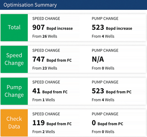
- Ensures that engineers can focus on optimizing the most profitable wells, (Fig. 11).
- Models CO2 behavior, so liquid volumes in the pump are better known.
- Calculates the point at which CO2 will flash, for maximum off-take.
- Monitors gas-lifted wells, highlighting those where injection is not at the orifice or where increased gas injection rates would boost production.
- Proactively alerts engineers to non-routine operating conditions.
- Helps predict pump failure.
Pump Checker is scalable, and works for small operators with a handful of pumps, or majors with thousands of wells. The results are consistent. Base production rises by between 5% and 10%, with individual well performance increasing by up to 30%. These returns make the device commercially viable in many applications.
VSD generates intelligent alarms. There are different ways of operating an oil field, from basic data monitoring to complex algorithms in automated systems. In the first case, the system reliability and production optimization rely on the skills and actions of the individual engineers that can be overwhelmed by large amounts of information that makes prioritizing actions difficult. With fully automated systems, the complex algorithms require highly skilled personal and often costly investments. While it may be cost-effective organizing the latter kind of support for large sites, it might not be the best fit for smaller sites.
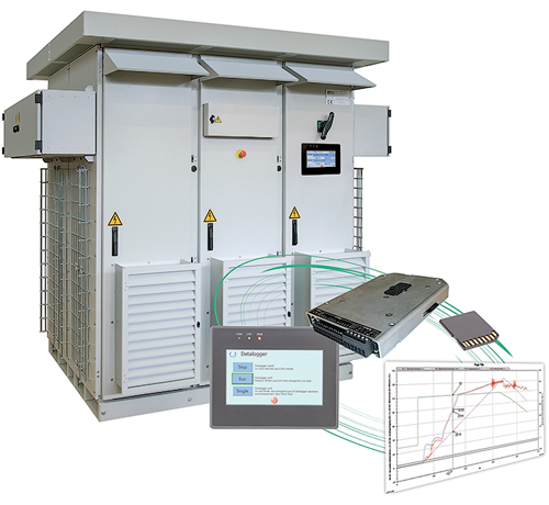
Leroy-Somer’s new variable-speed drives, with advanced data monitoring and logging (DML) features, provide an alternative solution that easily anticipates trips and failures for managing site operations, Fig. 12. The DML centralizes well data, including drive, downhole and head, in the VSD, where a powerful interface provides months of logging. This interface analyzes the data and flags deviations in logged parameters (programmable slope). Operators can define and prioritize combinations of flags to generate intelligent alarms, as required.
The amount of information communicated to the operator is reduced considerably, which improves reaction times. Producers can still validate an alarm by accessing the data, thus securing the corrective action. Overall, the Leroy-Somer Advanced DML can significantly reduce downtimes and workover costs.
Value-driven digital oil field. The objectives of a truly digital oil field (DOF) are maximized recovery, optimized production, improved operational efficiencies, enhanced knowledge base and minimized HSE incidents. The DOF is based on:
- Smart measurement and control systems in wells (subsurface and surface), networks and facilities,
- Capture, transmission and integration of real-time data from all assets
- Real-time data delivery, and
- Intelligent data processing.
The DOF has several challenges. More than 70% of the wells in the world are still not connected and monitored, and production loss in artificially lifted wells is significant (often more than 10%). Large operational staffs are still required to perform normal daily checks and maintenance on wells. Current technological solutions offered by automation and service companies are frequently too expensive, logistically complex and inefficient, requiring significant maintenance and support.
According to Evinsys, their WellLynx hardware and software platform provides the underlying infrastructure and technologies to enable a true DOF, offering a comprehensive approach that reduces deployment time, cuts maintenance and operational costs, increases uptime, and optimizes production. The WellLynx platform provides real-time data acquisition, data management, time-series history, business intelligence, data-driven analytics, HTML5 visualization and Internet-of-Things managed RTUs.
A comprehensive software and hardware solution, the WellLynx acquires, monitors, manages, analyzes, diagnoses and controls artificial lift assets-—all at a significantly lower cost, compared to conventional SCADA solutions.
The platform is scalable and deployable on public/private clouds or within private networks. The system features simple deployment, and is easy to manage and maintain. Key WellLynx advantages include:
- Scalable architecture.
- Built-in time-series historian with unlimited data retention.
- Rich HTML5 visualization with no client installation requirements.
- Data-driven, self-learning predictive equipment failure models.
- ESP diagnostics and analysis to detect gas locking, motor over/under load, plugged intake monitor, oversized pump, pump wear, submergence analysis and tubing leak.
- Smart caching to improve system performance (can display two years of data history).
- Multi-tenant capabilities.
- Multi-level user roles and privileges.
- Live data streaming with real-time global views and dashboards.
- Native iOS and Android apps.
- Built-in reporting engine.
- Utilizes fully-managed IoT RTU.
- Reduced communications costs 90% vs. traditional SCADA/MODBUS.
- Lowest fees in the industry.
WellLynx has been used to manage assets throughout North America and the Middle East, proving its value as a comprehensive DOF solution.
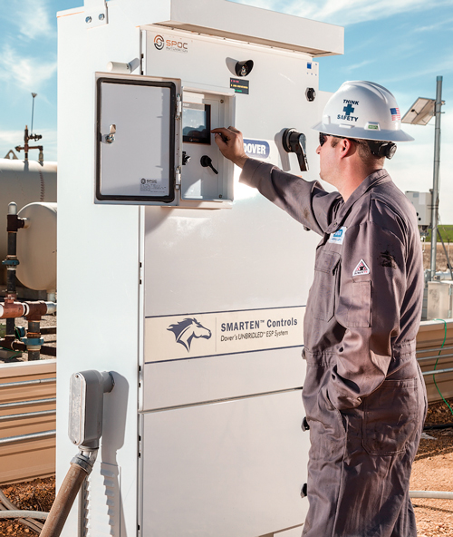
Cloud-hosted monitoring and optimization system. Dover Artificial Lift has introduced its LOOKOUT monitoring and optimization system powered by Theta Oilfield Solutions’ XSPOC software, Fig. 13. This new system delivers users a powerful tool for real-time monitoring, decision making, collaboration and well performance optimization. It’s controlled with a cloud-hosted system for ease of support and maintenance.
The system is tailored to the producer’s specific needs and economics, from simple on/off notifications to active monitoring scenarios targeting key performance indicators. Fostering collaboration and streamlined workflows, the system allows for easy access across a variety of platforms from mobile to desktop; and presents useful information, allowing for gains in production and lengthening lift system run time.
By leveraging the Theta’s XSPOC artificial lift monitoring system, LOOKOUT can be utilized on every form of artificial lift, including ESPs, rod lift, gas lift and others. Operators can pump by exception, where wells that are operating properly can be passed over in lieu of wells that are not operating properly. The system moves beyond alarming and set points, which force users into a reactive monitoring role.
However, by looking at a well model (comparing the ideal performance of both well and equipment, with the actual performance) the system can identify wells that could be operating more efficiently. Further enhancements include daily and monthly reports, all automatically generated, to make the user’s time more effective. The system enhances the way operators can view run life information by categorizing shutdowns into general causes and tracking the root cause of failures.
A key feature is the automatic diagnostics, utilizing the well equipment parameters and its real-time data. By comparing the actual flow from automatically imported well tests against the theoretical flow; diagnostics, such as pump wear or potential tubing leaks, can be proactively determined. Another feature that spans lift-type boundaries is the sizing score, providing the user with an accurate look at well conditions (based on IPR data) and equipment application, indicating if a re-size should occur at the next workover.
By automatically performing these calculations—whether it is exception reports, pump operating points, optimization based on system software diagnostics or well test uploads—the automated nature of the system helps accurately monitor, diagnose, optimize and ultimately increase recovery.
Dover suggests that the power of the system is not only in its automatic operation, but in the collaboration between their artificial lift experts and operators. Company experts will work with users to establish KPI’s, a generate a holistic approach to meeting those KPI’s. Finally, they will conduct weekly meetings, where performance is evaluated and adjusted to meet the operator’s objectives.
OTHER DEVELOPMENTS
Borets, an ESP engineering, manufacturing and service provider, has purchased an operations facility in Midland, Texas. The 11.2 acre site has 58,000 sq ft for manufacturing and service capabilities, and 10,000 sq ft of office space. The facility will accommodate assembly and dismantling operations, a full-service cable shop, sales and service teams equipped to serve customers throughout the Permian basin. ![]()

