A new approach to optimizing plug-and-perf completions
Oil and gas operators throughout North America’s shale plays have chosen the plug-and-perforate (PnP) method as the most common technique for multi-stage completions, and have accepted the method’s complexity to achieve better frac jobs and potentially higher production. Yet, as operators in unconventional fields strive to improve efficiency and reduce cost, they can save time and money by taking a new approach to optimizing PnP completions.
By following the recommendations presented in this article, operators can improve wellsite efficiency and safety, enhance the quality of their completions, save substantial operating costs, and bring their wells onto production sooner.
PLANNING PnP COMPLETIONS
Pre-job planning is critical to successful PnP completions. It is important to know the configuration of the cased well that will be perforated and fractured. This includes any casing ID variations, such as liner tops and patches, to be encountered during wireline operations and which should be considered when calculating annular fluid velocities. The well’s directional survey should be reviewed carefully to identify depths for the kickoff point, and 30°, 60° and 90° inclinations. If the well has been geosteered, it may have doglegs in the horizontal section, and these should be noted before the well is completed.
Before operations begin, the completion engineer should use the above data to model the well, using Cerberus software or an equivalent package to ensure that there is no interference with the toolstring in the wellbore, and to identify potential problems.
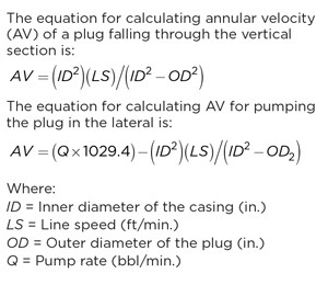
Our experience has shown that maximum safe running speeds for plugs are determined by annular velocity (AV), rather than by wireline speed or pump rate. Wireline operators and plug personnel also should be well-versed in calculating AV around the PnP string in collars, patches and liners, Table 1.
The well should be cleared of debris before PnP operations begin, as well as between stages. It is also critical to be aware of the fluids being used. For example, it is important to use the same fluid for flushing out the well that will be used to pump down the plugs, so there will be no differences in fluid viscosity that could affect pumpdowns.
Typically, the pumpdown method is different between single-well and multi-well operations, and job objectives and procedures must be adjusted accordingly. On single-well operations, pumpdown is usually carried out with the frac pumps, so there is significant incentive to save time by running the plugs as quickly as possible. With the right frac plugs and procedures, our firm has been able to reduce wireline run times by 70%, compared to previous methods. On multi-well pads, when perforating and fracing operations are run alternately between two wells, a single, dedicated pump can be used to run plugs with less water and at lower surface equipment cost.
Detailed procedures should be prepared to cover plug running, perforating and drill-out operations. These procedures should be distributed to, and discussed with, all personnel who will be working on location.
WELLSITE COMMUNICATIONS
Wellsite communications should begin during the planning stage. Wellsite personnel should be fully aware of the well configuration and completion design called for by engineering personnel in the office. The company representative should hold a pre-job meeting to make sure that personnel from wireline and pressure control, plug and pumping contractors have reviewed and understand all procedures applicable to them.
During operations, it is important for wireline, plug and pumping personnel to be in constant communication. Coordination between wireline and pump operations is critical to running plugs quickly, and to avoiding plug-related issues.
In addition to maintaining good communication, wellsite crews should take a disciplined approach to carefully recording parameters, including depths, flowrates, pressures, wireline speeds, etc., at every stage of the job. This information is vital for making decisions that prevent problems and optimize performance.
RIGGING UP PnP EQUIPMENT
The company representative should discuss safety issues with the crew before each shift, including keeping the key to the firing panel out of the wireline unit—until the guns are at least 200 ft below surface—and that radio silence should be maintained when guns are being wired, or when live guns are being pulled from the hole.
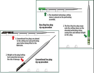
During rig-up with most composite plugs, the plug is made up to the setting tool on the perforating string, while the string is laid out horizontally on tool stands. This configuration makes it difficult to ensure that the setting tool piston is in the right position and does not contain trapped air. Installing a plug horizontally also increases the risk of damage to that plug, when it is lifted from the ground to the lubricator. If this procedure must be followed, a dolly should be used to support the plug and keep it from bending.
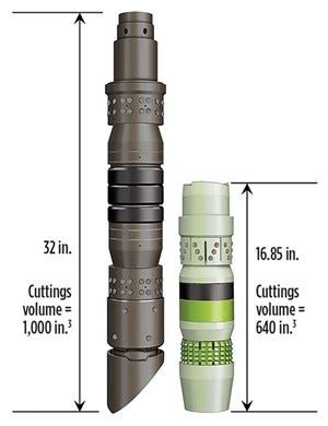
We designed our setting kit (compatible with both Baker and Owen setting tools) and its plugs to enable plug installation while the perforating string is in the vertical position. This permits the operator to more easily confirm that the setting tool is properly dressed, and enables faster makeup of the plug to the string, Fig. 1.
PLUG SELECTION
In wells employing the PnP completion method, operators are using tighter stage spacing, with 20 to more-than-100 plugs used during multi-stage fracturing. Therefore, a plug’s running, setting, ability to seal during fracturing, and removal, are critical features that can affect each well’s economics.
Most frac plugs are derived from cast iron plugs used for temporary zonal isolation, with slips and seals proven on retrievable packers. Composite materials were introduced in the 1990s to make plugs easier to mill—and other incremental design changes have been incorporated—but most plugs still resemble their cast iron predecessors. These plugs continue to pose operational problems, such as slow running speeds, excessive water use for pumpdown, premature setting, failure under pressure, and long drill-out times.
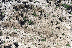
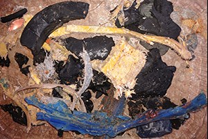
Our firm has introduced a new plug design, and a new approach to PnP operations, that enable plugs to be run at high speeds with less water consumption, Fig. 2. The Boss Hog frac plug is half the length and weight of typical frac plugs, with an up-to-15,000-psi pressure rating. It is constructed from filament-wound composite material, rather than from composite sheets or extruded components, and has a modular design with far fewer parts than previous plugs. During drill-out, the filament-wound composite is reduced to small, hair-like cuttings that are easily returned to surface, Figs. 3 and 4.
Unique features of the Boss Hog plug include a one-piece composite top slip with mild steel buttons, instead of tungsten or stainless steel, to prevent casing damage, and a cast-alloy lower slip that holds up to 15,000 psi of pressure and drills out into fine particles during removal.
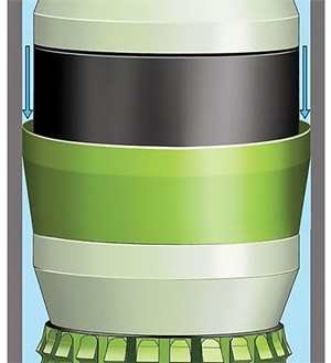
The plug also includes a fluid propulsion component that greatly enhances pumpdown efficiency, Fig. 5. The Heli-Seal system opens to capture water while pumping and safely propels the plug downhole at speeds of over 1,100 ft/min., while using up to 50% less water than is required with plugs that do not have a fluid propulsion module.
After perforating, the next step typically is to pump down a ball to seat the plug before fracturing. New ball-in-place plugs can save up to 30 min. per stage and eliminate water used for ball pumpdown. This also eliminates the worry of pushing away the already placed near bore proppant on the previous stage. Plugs with this feature also provide the capability to pressure-test plugs before fracturing and provides the ability to break down the first few clusters that normally don’t get broken down. Unlike ball check versions, the ball can be circulated back to surface in the event that the guns do not fire. Where low pressures and the ability to flow the ball back are a concern, there is an option for disolvable ball avoiding TCP or tractor runs, Fig. 6.
RUNNING PLUG PROCEDURES
To gain the efficiencies of new plug designs and associated running procedures, wireline operators need to understand and implement new operating procedures that challenge long-held assumptions about running and setting composite frac plugs.
Manufacturers of older frac plug designs recommend that plugs should not be run at speeds faster than 250 ft/min. Our new-generation plugs can be safely run at speeds in excess of 1,100 ft/min., when they are deployed with the new procedures.
The key to increasing the speed and reliability while running composite plugs is to base the operation on the AV of the fluid flowing past the frac plug and perforating assembly, rather than on the pump rate. Traditionally, plug suppliers have provided tables correlating pump rate and pumpdown speed for plugs of given diameters running in various casing sizes. The values in these tables seldom match actual running rates, so they can only provide a rough approximation of what wireline operators can expect.
Annular velocity is a much more accurate and predictable parameter during PnP operations. In calculating annular velocities, it is important to take into account any changes in casing ID, liner tops, patches, high deviations, etc., because these changes affect the AV as the PnP assembly passes through the reduced or increased casing profile.
When properly weighted, the toolstring can be allowed to fall with gravity in the vertical section. We recommend keeping the annular velocity below 3,500 ft/min. while running through the vertical hole, so maximum plug-running speeds can reach between 350 and 700 ft/min. without pumping, depending on casing size and plug diameter. Some operators use the ball-in-place option to directly spot acid on the clusters when perforating. By using this method, it is best to pump the acid followed by the column of fluid in the vertical. When doing this, it greatly reduces the the AVs and can allow much greater speeds while pumping in the vertical section of the well. Care should be taken during the first run into the well to avoid unexpected obstructions. Line speed must be reduced when traveling through changes in casing ID, and when traveling in and out of liners.

Setting depths should be confirmed with the company representative. Plugs should be pumped past the setting depth, but not into the perforations of the previous stage. Once on depth, the pump rate should be held at 2 bbl/min. This ensures that the line will be kept in tension, and the plug will not move before being set. At this point, the wireline can be pulled back slowly to the setting depth.
SETTING PLUGS
A setting tool can be used for thousands of runs in its life span; however, it is important to document each run and get certified every 1,000 runs or less. Proper power charge selection is an important factor in successful plug setting. Plugs like the Boss Hog model are set in a two-step process. We recommend using standard charges with 10-to-40-sec setting times, because fast-acting charges may set plugs too quickly for them to set properly. Slow charges include additives to slow their activation, and tend to be brittle and prone to cracks and voids. Slow set charges also contain a small pill, like a secondary charge, that can fall out of place and keep the charge from burning. Both problems can prevent the setting tool from releasing its full power and make the tool more likely to not shear properly in horizontal wells.
When setting plugs with the ball-in-place feature, operators should pump at 2 to 3 bbl/min., to keep the ball in its seat during the setting process. Once the plug is set, a 100-to-200-lbf line weight loss and a 200-psi pressure increase will be noted at surface.
PERFORATING RECOMMENDATIONS
We recommend pumping at 2 bbl/min. and perforating “on the fly” while coming out of the hole at 30 to 40 ft/min. Pump pressure and string movement help prevent hanging up the guns in accumulated debris or sticking differentially. Ball-in-place plugs allow the operator to over balance the well before perforating the first cluster, then increase rate on each of the next couple shots, forcing these clusters to get fully broken down.
PLUG DRILL-OUT
After all stages have been stimulated, the composite plugs have to be drilled out to establish a clear casing ID for production. Shorter, lighter-weight plugs can be drilled out in about half the time required for previous composite plugs.
Before drill-out operations, we recommend using Cerberus software (or a similar package) to model the expected performance of the coiled tubing string and BHA proposed for use on the drill-out. The software helps specify chemical programs for debris removal and determines whether the string and available circulation can remove all plugs, including those near the toe, without getting stuck.
In most wells with 5.5-in. casing, a 2⅜- or 2⅝-in. CT string is recommended, instead of the more common 2-in. coil size. The larger coil enables high flowrates and use of 3⅛-to-3½-in. OD even wall downhole motors with slow-speed, high-torque power sections. These mud motors can drill out plugs without stalling, and can handle high enough flowrates to create AVs of 240 ft/min. or higher, to effectively circulate cuttings back to the surface.
The drilling bit/mill should be gauged at 99% to 100% of the casing ID drift, as it provides full coverage of the plug and prevents production of larger debris, as well as coring of the plug. A sealed bearing roller cone bit is recommended, as it produces consistently smaller cuttings. This is due to its rotary crushing action of three points, versus a shearing action enacted by one solid cutting interface of a mill. With more innovative designs of sealed bearing roller cone bits, the longevity of the bit has greatly improved—especially in 5.5-in. or larger casings. In a 4.5-in. casing, a sealed bearing roller cone bit may still be used in conjunction with a low-speed, high-torque motor, as well as drilling best practices of minimum weight-on-bit (WOB). This reduces the risk of overheating bearings and potentially losing a cone. New mills—specifically designed for plug drill-out operations—have performed better than previous five-blade mill designs. This is due to their less aggressive facing and smaller water courses.
Until recently, standard practice during plug drill-out operation was to perform short trips—pulling the CT string out of the horizontal section, while circulating gel sweeps to effectively clean the hole and prevent sticking. In addition to taking several hours for each trip, this practice reduces the working life of the CT string and increases the overall water and chemical volume for the operation. To eliminate short trips, WOB is kept to a minimum during drill-out to achieve small particle cuttings. Light to moderate viscosity gel sweeps are timed carefully, so that they exit the bit as the plug finishes drilling. This helps entrain all the cuttings and facilitate an effective cleanout.
Flowback is also a key component to drill-out success. Ensuring that the flowback rates are matching—if not slightly exceeding the pumping rate (underbalanced), without drawing in from formation throughout the overall operationis critical to maintain turbulent flow throughout the wellbore. Turbulence allows continuous entrainment of the solids into the main flow regime, to effectively transport the cuttings back to surface. This operation requires close cooperation between the CT operator, pump/chemical supplier and flowback operator. The extra effort can result in significant improvements in efficiency and lower overall cost, as well as achieve earlier production from the well. For example, our company has recently worked with numerous operators in the Rockies to safely reduce drill-out times from 36-60 hr to 10-12 hr.
CONCLUSION
The PnP operation is the completion method of choice in many unconventional basins throughout North America. By optimizing job planning, wellsite coordination, plug selection, running and setting procedures, and drill-out and debris removal processes, operators can realize significant savings in time and cost, while improving productivity from their wells.
Table 2 shows typical savings that can result from using new frac plugs, and following recommendations presented in this article. The new frac plugs have been used successfully to complete more than 100,000 stages. ![]()
- Coiled tubing drilling’s role in the energy transition (March 2024)
- Shale technology: Bayesian variable pressure decline-curve analysis for shale gas wells (March 2024)
- What's new in production (February 2024)
- Using data to create new completion efficiencies (February 2024)
- Digital tool kit enhances real-time decision-making to improve drilling efficiency and performance (February 2024)
- E&P outside the U.S. maintains a disciplined pace (February 2024)

