Evaluating diversion techniques to increase stimulation effectiveness in the Eagle Ford
A number of studies and publications have investigated cluster efficiency in multi-cluster stimulation treatments in unconventional reservoirs, using both production logs and fiber optics. The results of these publications reveal that a major challenge, with simultaneously stimulating multiple perforation clusters in a single treatment, is ensuring that the fluid and proppant are equally distributed between all clusters. One technique used to confront this challenge has been to deploy a biodegradable particulate diverting agent into the stimulation treatment, to redistribute fluid and improve cluster efficiency.
In the Eagle Ford shale, 61 wells were selected for a controlled study: 13 of the these wells used the diverter material and 48 were used as control wells. In addition, one of the diverter wells incorporated fiber-optic technology, to provide extensive diagnostic and reservoir characterization, to gain subsurface understanding of the effectiveness of the diverting agent.
Project location. The study was performed in Texas’ La Salle and McMullen counties in the volatile oil window of the Eagle Ford shale. The 61 wells in the study were in five different areas, which were strategically chosen to investigate the impact of the diverter in various phases of reservoir development. To understand how various reservoir conditions affect the effectiveness of the diverter, wells were selected in both undisturbed reservoir and in areas in close proximity to the drainage areas of existing wells. Stimulating wells in close proximity to existing, producing wells adds its own set of challenges, including well-to-well interference and its effects on the stimulation effectiveness. Well interference and loss of fracture efficiency, from pressure sinks caused by offset wells, will appropriate fracture energy and therefore reduce reservoir stimulation effectiveness.
CLUSTER EFFICIENCY
Perforation cluster efficiency can be defined as a metric quantifying the effectiveness of initiating fractures and placing proportional treatment volumes in all of the intended perforation clusters during a fracture stimulation treatment. A high cluster efficiency would mean all clusters, in a given fracture treatment interval, receive equal amounts of fluid and proppant, creating uniform fracture half-lengths.
As operators attempt to reduce unnecessary costs and improve production by treating more clusters per stages, it is important that stimulation cluster efficiency is understood, and methods are put in place to help reduce the percentage of understimulated clusters. Also, as wells are drilled on tighter spacing, it is imperative that fracture stimulations be kept as close to the designated drainage area as possible, to maximize near-wellbore complexity and, correspondingly, oil recovery within the drainage window. The use of diverters can help increase near-wellbore complexity and prevent the creation of longer fractures that would stimulate rock normally stimulated in the offset well.
Wells that are drilled adjacent to offset production face a different challenge. The pressure sink created within the designated drainage area of an offset well, combined with fractures created that extend past the drainage area of the well, create potential paths for the loss of fracture energy pumped into new wells. The use of a diverter, to plug the path of least resistance in the established drainage area of the offset well, can improve the overall fracture efficiency and optimize the stimulation of the new well’s designated drainage area. An indicator of success is that the wells closest to the established offsets will have a similar cumulative production vs. flowing tubing pressure as the new offset wells that are farther away from the established production.
DIVERTER APPLICATION
The diverting agent was introduced into the stimulation design for this study without necessitating any modification to the standard design variables of proppant volume, proppant concentration, fluid volume, fluid type, treatment rate and perforation scheme. The design consisted of six clusters per stage, spaced 40 ft apart, with approximately 1,600 lbm of proppant per lateral foot. For the diverter wells, the treatment was divided into two proppant ramp segments with a diverter drop separating them. The diverter was deployed after concluding the proppant schedule ramp of the first portion of stage treatment. Before the diverter reached the downhole perforations, the rate was reduced to seat the diverter. Once a pressure indication was observed, the rate was increased and the second segment of the treatment was pumped. This method was deployed on each stage of all 12 of the wells in the diverter well subset, excluding the diagnostic well, in which variations of the deployment were executed.
PRODUCTION RESULTS
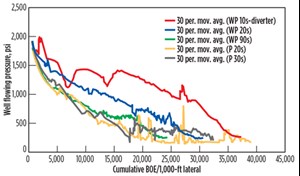
The wells were produced with a managed choke schedule that maintained a similar, constant flowrate for all wells. Because of this, the production metric used to determine diverter effectiveness was the well flowing pressure vs. cumulative BOE/1,000-ft lateral. The wells that maintained higher flowing pressures, through the controlled production process, were recognized as the better performers. The flowing pressure was plotted as a 30-day moving average, and, in some cases, multiple wells were averaged together when drilled on the same pad.
All wells were completed with the same perforation scheme and stimulation design. Variables—such as clusters per stage, shots per foot (sp/ft), stimulation rate, fluid type, fluid volume per lateral foot, and proppant per lateral foot—were held constant for all wells during the study. The only completion variation was the introduction of the diverting agent.
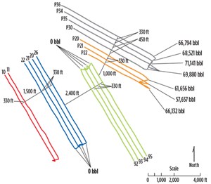
Area 1 consisted of two diverter wells (Wells 10 and 11) and 15 non-diverter wells, Fig. 1. All wells in this area were drilled with 330-ft well spacing, except for the P30 well, which was drilled with 450-ft spacing. The non-diverter wells were drilled over four pad locations, with the P20s and P30s first production on 8/2014, the 20s first production on 3/2015, and the 90s first production on 5/2015. The two diverter wells first production was in 1/2015, after the P20s and P30s, and before the 20s and 90s.
Figure 2 shows the average flowing pressure for each pad. The diverter wells outperformed all other wells in this area, by flowing at a higher pressure, at an equivalent cumulative production, indicating improved cluster efficiency and reservoir contact.
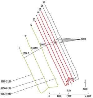
Area 2 consisted of four diverter wells (Wells 20, 21, 22, and 23) and 5 non-diverter wells, Fig. 3. The 10s pad was the first to begin producing on 4/2012, and the 20s pad, which included the diverter wells, began producing on 10/2015.
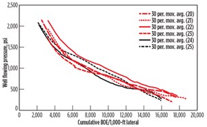
Figure 4 shows a comparison of all wells on the 20 pad. Well 12 is offset to the 20 pad by 500 ft, and produced 238,239 bbl of oil by the time the 20 pad began producing. Because of the proximity of Wells 20 and 21 and the pressure sink induced by offset production, it was expected that the fracture effectiveness would be impacted by the fracture wings growing into drainage areas of offset wells. However, the flowing pressure results actually show Wells 20 and 21 to perform similarly to all other wells on this pad. This proves the concept that the diverting agent is reducing the effects of fracture interference, and loss of fracture efficiency from pressure sinks induced by offset wells, by distributing fracturing fluid more evenly to all perforation clusters, reducing the fracture extension into the drainage areas of the offset wells, and redirecting the fracture energy to a closer proximity to the intended well being stimulated.
Well 22 outperformed all other wells in this pad, and it should be noted that this was the well that used fiber optics for real-time stimulation optimization and design improvement. By monitoring cluster efficiency in real time, design changes were able to improve cluster efficiency and ultimately the productivity of this well.
FIBER-OPTIC DIVERTER RESULTS
The well study using fiber optics consisted of 31 total stages, with 22 of them incorporating the diverting agent. For analysis of the diverting agent, DAS was the preferred tool to determine effective diversion, because it allows for a temporal and real-time view of flow distribution.
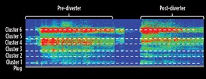
Throughout the stimulation of this well, different methodologies were applied to the diversion deployment process for understanding and optimization. Overall, some stages showed a positive diversion response, while others produced a minimal shift in flow distribution. For those showing a minimal response, Fig. 5 illustrates the DAS response, where a nominal shift in acoustic intensity is observed before and after diverter treatment. In this example, the flow percentages to each cluster do not change significantly, even after the diverter treatment. While this diversion response was not expected, it indicated that, in the cases where the diverter did not appear to work effectively, no detrimental impact could be observed to the cluster efficiency of the stage. This also establishes that cluster efficiency improvement is not guaranteed simply by incorporating diversion product into a stimulation treatment.
The majority of the stages that showed this minimal shift in acoustic intensity occurred early in the well completion, during the initial treatment stages. This allowed for the engineering group to analyze the real-time DAS response of these first stages and implement design changes to improve the diverter response.
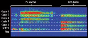
The design changes primarily focused on deployment of the diverter and the perforation scheme. Changes made to the deployment of the diverter included concentration, injection rate, seating rate and volume. The perforation scheme was also adjusted to alter the initial flow profile, as well as improve diversion efficiency. These design changes produced improved diversion responses. Figure 6 is an example of a stage where a positive diverter response was observed in the DAS data.
CONCLUSION
Through production analysis of multiple areas and permanently installed fiber-optic cable, the following conclusions were drawn:
DAS and DTS data showed that, in most cases, fluid is not evenly distributed to all clusters, leaving many clusters over-stimulated or under-stimulated.
Production data from the five areas showed that the diverter wells outperformed the control wells in most cases. The improved performance indicates that the diverter allowed increased cluster efficiency and reservoir contact.
Wells drilled near offset producers showed better-than-expected performance when using the diverting agent, suggesting the diverter improved fluid distribution to each perforation cluster and reduced fracture energy loss, by diverting the fluid from the drainage area of offset wells into the targeted drainage area of the newly drilled well.
Results from the fiber-optic DTS and DAS analysis provide validation of diversion effectiveness and aided in optimizing the diversion process.
Diverter effectiveness can be difficult to determine based on surface responses, and diagnostic tools, such as downhole fiber optics, are helpful to fully understand how the diverter impacts a treatment stage.
Deploying diverter with an engineered approach and increased subsurface insight led to improved results and more effective diversion.
The remaining three areas, which were investigated in this study, produced similar results and conclusions to those found in the two areas discussed in this article. ![]()
ACKNOWLEDGEMENTS
This article is an adaptation of URTeC paper 2459883.
- Shale technology: Bayesian variable pressure decline-curve analysis for shale gas wells (March 2024)
- Using data to create new completion efficiencies (February 2024)
- Prices and governmental policies combine to stymie Canadian upstream growth (February 2024)
- U.S. producing gas wells increase despite low prices (February 2024)
- U.S. drilling: More of the same expected (February 2024)
- U.S. oil and natural gas production hits record highs (February 2024)

