Efficient, multi-zone testing enhances re-frac design and implementation
In the early stages of horizontal drilling (circa 1990s), operators were struggling to understand production profiles, drainage, skin damage and other aspects of producing from a horizontal wellbore. Most of these early horizontal wells were open-hole completions in carbonate reservoirs.
To define the production profile, plan workovers to reduce undesirable production, and stimulate overall output, a multi-zone testing tool was developed. The tool proved to be an efficient, inexpensive means of performing tests on selected intervals in the lateral, and its use was extended to multi-lateral wells.
Initially, the tool string consisted of a re-settable control head, two inflatable packers spaced apart to achieve the desired test interval length, a safety joint and other accessories. This accommodated a variety of potential problems thought to be prevalent in horizontal, open-hole operations.
Most field operations were conducted to determine the source of undesirable fluid entry and then develop plans to modify inflow. In numerous cases, skin damage was detected, and it was removed with matrix acid treatments, to enhance the production rate. Deployment of these treatments used the same testing tool.
Once the tool system was proven to be reliable, safe and efficient for performing multiple tests on a single trip into the well, operators began to add pressure and temperature recording gauges to the test string to enhance data quality.1 Swabbing was initially preferred as the artificial lift method, due to low cost and availability on most workover rigs. Drawdown and buildup analysis were difficult, due to the fluctuations and instability of the producing BHP.
To overcome the pressure surging aspect associated with swab testing, the straddle tool assembly was fitted with a hydraulic jet pump, and a means to achieve downhole shut-in after producing at a stable rate for a finite period. The system was described in articles published in both trade journals and technical meetings.1,2
The industry now finds itself in a similar situation with respect to re-frac operations in existing unconventional resource wells. A better understanding of flowrates, fluid composition, skin damage or mechanical plugging of each zone should yield better, more cost-effective designs for the re-frac stages. In early, horizontal open-hole testing, proven benefits of understanding reservoir segments were reducing overall costs and improving economics of remedial operations.
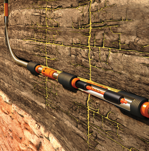
Figure 1 illustrates the basic tool string concept, using an inflatable packer straddle and associated tools for testing across a frac port with swell packer zone separation. In this configuration, produced fluid is exhausted above the jet pump and into the open annulus, thus entering other open intervals. Some objections to this aspect of the tool feature have been expressed, but considering the system’s simplicity and the fact that the next planned operation will be to inject fracturing fluids into these receptor zones, these objections are becoming less of an issue.
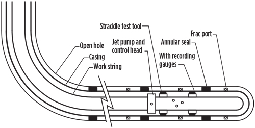
This simple, two-packer tool string, shown in Fig. 2, would include:
- Work string (coiled or threaded tube)
- Control head for packer setting (inflatable or hydraulic compression type)
- Hydraulic jet pump with check valve
- Pressure/temperature/flowrate memory gauge
- Safety joint
- Unloader valve, up to open
- Top packer
- Interval spacing, as required
- Bottom packer.
Note: Pending the straddle tool provider’s capability, a bypass can be included in the system to maintain equalization of pressure, above and below the packers.
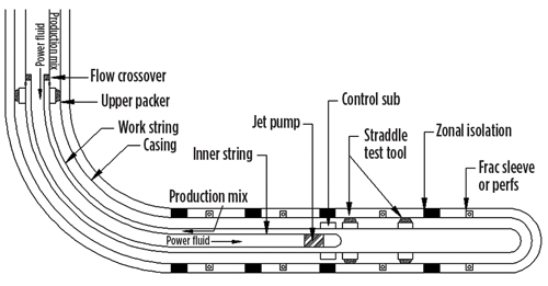
A tool string with a more complex, three-packer, configuration is available, as shown in Fig. 3. This configuration adds a third packer positioned above all open intervals, and an inner string to place the jet pump and downhole shut-in tool immediately above the straddle packer section. This system directs produced fluids into the annulus, above the top packer, with returns to the surface. Produced fluids can be sampled, and production rates determined, in a very short test period. As an example, using a routine power fluid rate of 2 bpm in a 2 3/8-in. tubing by 4½-in. casing completion at 8,000 ft, TVD, produced fluids are received at the surface (mixed with power fluid) in less than an hour after initiation of the test.
The field operation of either system is as follows:
- Run the tool string to straddle the first desired test interval.
- Initiate pumping, to create a differential pressure across the jet pump nozzle. This differential pressure expands the packers.
- Downward motion of the work string locks the packers in the expanded position and communicates the test interval to the jet pump intake.
- Power fluid pump rate is increased to achieve desired drawdown and held for a finite time, as planned or determined during the test.
- Pumping is terminated, which automatically achieves downhole shut-in at the test interval, as the check valve below the pump closes/seats. Wellbore storage effects are eliminated from the pressure buildup analysis, and overall test time is reduced.
- Once the shut-in period has been achieved, upward movement of the work string unsets the packers and allows movement of the tool string.
- These steps can be repeated for all desired intervals.
Note: Injection—fall-off testing or slug testing can be achieved in lieu of production/buildup testing, if desired, with a slight modification of the downhole shut-in valve configuration.
Production decline associated with unconventional resource wells has generally been attributed to drainage of the reserves from the low-porosity, low-permeability, artificially fractured zones. Efficient multiple-zone well testing can demonstrate a variety of causes for reduced production, such as:
- Efficient, initial completion and fracturing treatment, resulting in desired reserve recovery
- Ineffective initial fracturing treatment, with poor reserve recovery
- Loss of proppant in the near-wellbore fracture, thus reducing inflow performance. This case may be from poor placement of proppant near wellbore, over flushing of proppant or flowback of proppant, prior to complete fracture closure
- Plugging of the near-wellbore fracture, due to fines migration or proppant crushing
- A variety of causes resulting in plugging of perforations, frac ports or annulus, thus limiting fluid movement into the well
- Premature closure of a frac port.
Items 2 through 5 of the described causes of reduced flowrate and/or recovery may be treated easily with low pump rate and low proppant volume treatments. The straddle configuration used for testing (without jet pump) can be used to achieve lower rate repair treatments, with multiple zones treated on a single trip into the well.
Field experience has shown that drilled-out frac sleeves are far from smooth, and have damaged a variety of packer types run through sleeves, even after effective scraper runs. The recommended straddle with the highest success rate and re-set cycles consists of an inflatable assembly, with an element providing a minimum clearance of ½-in. between the packer OD and the casing ID. Centralizers positioned above and below each packer, with clearance of less than ¼-in., reduces element damage, due to the typically jagged condition of the drilled-out frac ports.
In the most effective operation of the tool assembly, a means should be provided to expand, lock in the set position, and open to the test interval with simple up/down work string movement. In addition, the tool should include a mechanism, such as a check valve, to accomplish downhole shut-in for elimination of afterflow effects during the buildup segment of the test. Once the test has been completed, up/down work string movement must release the packers after equalizing pressure between annulus, work string ID and producing intervals. If these operating criteria are met, coiled tubing can be utilized as the work string for even faster testing operations. ![]()
REFERENCES
- Cormier, K., et al, “A multiple-zone acid stimulation treatment of a horizontal well, Midale Saskatchewan,” JCPT, Nov. 11, 1991.
- Padilla, A., and J. Miller, “Locating and controlling water production in horizontal wells (Permian basin),” Southwestern Petroleum Short Course, Texas Tech University, April 2000.
- Stokley, C. O., and R. Jackson, “Innovative applications emerging for hydraulic jet pumps,” Petroleum Engineer, June 1998.
ACKNOWLEDGMENT
The author would like to thank TAM International for contributing artwork, editing, and assistance in recovering the aged reference articles.

