Offshore innovations boost efficiencies, solve subsea problems
This year’s collection of new technologies and new-generation improvements on existing products covers a wide swath of equipment and functions, ranging from expandable liners, liner-hangers and ratchet collars, to submersible pumps, subsea compression and water analysis sensors. Readers will notice a definite underlying theme related to subsea functions, which, in addition to some of the aforementioned items, also includes BOP control systems, subsea fittings and a hybrid ROV. Three of the products in this section are also OTC Spotlight on Technology award-winners.
ESET—An enhanced SET system
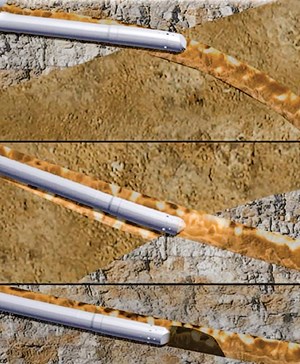
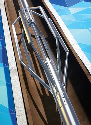
ESET, the industry’s only solid expandable liner that can be rotated and reciprocated, increases the operating envelope of solid expandable tubulars, Fig. 1. Advances in directional drilling technology have caused wellbores to become more tortuous, ultimately creating challenges that accumulate nonproductive time (NPT) for operators. Ledges, highly deviated, long-reach, and equally difficult well geometries are challenges that can stop conventional, expandable liner runs short of the target setting depth.
To address these challenges, Enventure added an eccentric guide nose on the ESET liner, to help guide the tool over ledges in the wellbore, minimizing time and increasing the probability of the liner reaching the target setting depth. High-torque connections enable rotation of the liner and minimize the risk of connection back-off or connection make-up downhole, either of which could lead to pressure losses while expanding the liner and, ultimately, the accumulation of NPT. Enventure modified the launcher and inner string to handle the increased torque and reduced the number of internal connections, while increasing the make-up torque of the internal connections. The new ESET inner-string components have been tested to 40,000 ft/lb of torque.
Typically, the ESET system is tripped in the hole conventionally, and it only begins circulation and rotation to confront ledges, dips and other wellbore tortuosity issues. Unlike a standard non-rotational SET solid expandable liner, where the progress can be halted while encountering a ledge or increased friction in tortuous extended wellbores, the system can then be rotated to help it across the ledge, or out of the well cavity, and continue toward targeted depth. Wellbore clean-up will be improved, with the ability to rotate, to help deliver a clean wellbore for expansion. Once at bottom, rotation will work to promote a turbulent cement flow, to help enhance the integrity of the cementing job and the shoe test.
Oceaneering adds eNovus to ROV fleet
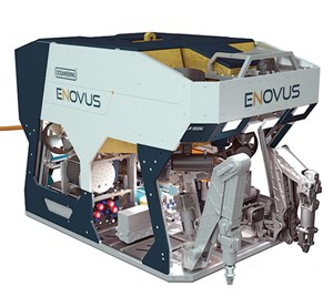
Oceaneering International has introduced its latest remotely operated vehicle (ROV), eNovus. The ROV will serve as the basis for a future hybrid between the autonomous underwater vehicle (AUV) and ROVs.
Complemented by features, such as Oceaneering’s Remote Piloting and Automated Control Technology, exhibited in the NEXXUS ROV, the eNovus will enhance the user interface, and reliability to perform both common and complex subsea tasks.
The vehicle has a modular, non-corrosive chassis, allowing for ease of tooling integration, and it is designed to withstand extended periods of time subsea, with little to no maintenance required.
eNovus is an environmentally conscious alternative to conventional ROVs. The majority of unauthorized environmental releases can be attributed to the main hydraulic circuit driving thrusters and tooling on standard work-class ROVs. In response, eNovus removes this risk and is powered by a 172kVA, fully electric propulsion system. Seven independent, variable drives provide increased power efficiency and allow for precise control of the vehicle, while an eighth drive is dedicated strictly to auxiliary tooling.
Additionally, eNovus offers all-electric tooling options, via an electric tooling control unit, manipulator tool changer, and all-electric tooling suite, Fig. 2. The electric tooling control unit provides multiple power outlets for tooling connections, as well as serial and ethernet communications dedicated to onboard and subsea interchangeable tools. Conventional hydraulic tools can still be operated by the isolated tooling power pack onboard the vehicle.
The ROV’s control system has full voltage and current feedback for ease of troubleshooting. The eNovus allows Oceaneering to identify, and rectify, technical problems, should they occur, while the ROV is still performing clients’ tasks.
Further efficiencies are realized with the use of Oceaneering’s Automated Control technology and manipulator tool changer. Electric and hydraulic tools can be changed out, subsea, without the requirement to return to surface. With the advanced technology of Supervisory Control, eNovus has capabilities to supplement and enhance pilot skills, by using Vision Control Software to function the ROV’s manipulators and thrusters.
Subsea gas compression has magnetic bearings
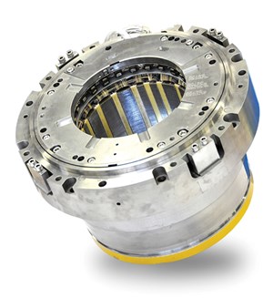
SKF has supplied magnetic bearings for use in the world’s first subsea gas compression system at Åsgard field, off the Norwegian coast. As part of this system, the bearings will contribute to recovering additional gas volumes from depleting gas fields, as well as extending the lifetime of those gas fields that would otherwise be closed prematurely.
Traditionally, gas compression occurs on platforms. For Åsgard, Statoil decided to locate it on the seabed, near the wellheads, to maximize gas recovery and, therefore, prolong significantly this field’s production lifetime. This technology reduces overall investment costs and CO2 emissions, when compared to conventional offshore facilities.
SKF’s magnetic bearing technology was a key enabler in achieving this autonomous, deepwater, subsea gas compression system, Fig. 3. The bearing simplifies the system architecture by removing the need for components, such as lubricating oil, seals and gearbox. The magnetic bearings are integrated inside the compressor casing, preventing gas leakage and allowing a smaller environmental footprint. Furthermore, the magnetic bearings are frictionless, enabling higher rotation speeds, leading to smaller compressor modules and ultimately lighter processing plant infrastructure.
Thus, the magnetic bearings enable the gas compression system to be completely oil-free and very reliable. Two 15,400-hp integrated motor compressors operate at a wide range of speeds, from 2,000 rpm to 7,200 rpm, at 300 m below sea level.
In addition to supplying the magnetic bearings, SKF also has provided a unique seven-axis control system that enables remote control of the magnetic bearings. This facilitates the effective, efficient use of the magnetic bearings through the production life cycle.
Lightweight VIV suppression system
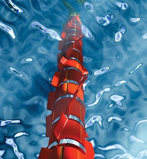
The Tri-Strakes Combi, a vortex-induced vibration (VIV) suppression system, was developed by Trelleborg to complement the high performance, S-Lay capable Tri-Strakes Stinger system and the cost-effective Tri-Strakes Lite system.
Because pipelines unsupported over free spans are prone to VIV fatigue—potentially leading to serious issues, such as pipe girth weld failure or premature pipe malfunction—Tri-Strakes Combi combats this with overlapping and interlocking moldings, with three-start helical strakes. The moldings provide an effective triangular or trapezoidal strake profile.
The company utilized its offshore and VIV knowledge in the design of the Tri-Strakes Combi, and carried out extensive computational analysis and physical testing. The system’s lightweight construction provides operators with a simple, rapid assembly method. The customized high-endurance material provides added resilience and load-bearing capacity, easing installation, Fig. 4.
Each section of the system was designed as a lightweight hinged component, ensuring it is quick and easy to pre-install onshore or offshore. Additionally, the modular design enables the system to be stacked during shipping, ensuring more efficient and cost effective transportation.
The system is temperature-resistant up to 140°F, in addition to being high-impact and abrasion-resistant. It is available with anti-foul coating or paint to protect against marine growth buildup, particularly in shallow-water environments.
The innovative manufacturing process also means that the system can be produced up to three times faster than systems manufactured using traditional techniques, reducing tool turnaround and manufacturing times.
Hard surfacing cuts drilling costs
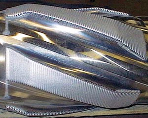
In the midst of the most severe downturn in the last 20 years, all of the major service companies are trying to save money. Technogenia is involved in some key areas that can have a direct impact on a rig’s operating cost. The company not only can protect newly manufactured drilling tools, but also repair existing ones. This makes it especially valuable, when your technology can be used on very expensive LWD or MWD tools. The lifespan of the tool can, therefore, be multiplied.
Technogenia can help to solve wear problems, using either the latest laser cladding technology or the more traditional oxygen acetylene processes, Fig. 5. The laser offers the advantage of controlling the heat input into the part, so that it can be repaired not once, but many times.
Each of the company’s seven Lasercarb centers is situated strategically to provide efficient customer support. The company’s headquarters, in France, host the R&D center, where a unique, spherical-cast tungsten carbide, under the name Spherotene, is produced. This metallic powder is produced, using a patented process called “cold crucible.” The spherical-cast tungsten carbide exhibits hardness of 3,000 HV +/-500 and, packed together, produces a high-density deposit. Technogenia can produce anywhere between -40 microns of powder, all the way up to 2 mm, depending on the application.
The powder is then incorporated into various welding consumables, under the names Technosphere and Technodur. Technosphere is particularly well-suited for a fixed-cutter, steel body bit or PDC; Technodur is more dedicated to drilling tools and stabilizers.
Finer-powder particles, under the name Technolase 40S, are used for the company’s laser cladding process, called LaserCarb. This fully automated process, developed by Technogenia in 1992, is perfectly adapted for non-magnetic stainless steel tools or complex geometry. Its accuracy makes it very well adapted for high-quantity production.
Technogenia can weld either external or internal surfaces. The company is capable of reaching over 30 in., deep, through a 1.5 in. internal diameter, and its in-house grinding capabilities bring parts to their final size. The company’s internal cladding work recently received a patent for the manufacturing of a downhole mud motor radial bearing, a key component for directional drilling.
Liner-hanger improves deepwater reliability
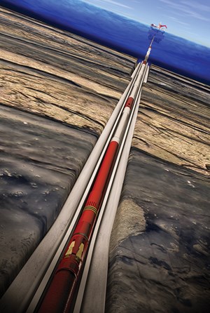
The SwageHammer integrated liner-hanger system reduces leak potential and improves reliability in HPHT, high-angle and deepwater wells. It combines the features of conventional and expandable liner-hanger technologies in a single-body system, Fig. 6.
The integrated liner-hanger system combines a high-performance, liner-top packer with a hydraulic-set hanger, as well as a tie-back polished bore receptable (PBR), all of which are run together as one integrated package. This enables a single hookup procedure, and a single stabbing and testing process, reducing installation and nonproductive time. The SwagHammer running and setting system is specifically designed to be used with this liner-hanger system.
The hydraulic running and setting system maintains balanced pressure throughout installation of the integrated liner-hanger system, enabling the liner system to withstand high circulation pressures and sudden surge pressures, without prematurely setting the hanger. This hydraulic activation eliminates the need for drillstring manipulation—which is required to set mechanical hangers—and enables setting of the hanger in deep, highly deviated wells.
The liner-top packer features patent-pending SwageSet sealing technology, which consists of a metal ring, with integral Aflas seals, which expands outward to form a reliable, anti-extrusion, gas-tight seal. The Aflas elastomers resist swab-off and promote high circulation rates. The packer is ISO 14310 V0-rated, meaning it is engineered to the strictest sealing criteria.
The tie-back PBR provides a means of tying back into the system, and houses the running-tool assembly to prevent damage during run-in, cleanup and cementing operations. It includes an anti-extrusion seal that can withstand high pressures; a cementing packoff that provides a positive seal during cementing operations; and a profile for a barrier that prevents debris from accumulating on top of the running and setting tools.
The system is rated up to 400°F (204°C) and 12,500 psi (86.2 MPa), making it validated for use in critical well applications that require enhanced pressure and temperature capabilities.
Ratchet collar prevents movement on casing
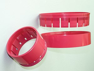
The patented Ace Ratchet Collar (ARC) from Ace Oil Tools secures accessories to casing or liner strings without troublesome set screws, Fig. 7. Each ARC features a male and female piece that are press-fit together to anchor the ARC to the base pipe, preventing accessories from moving, even under axial loads exceeding 90,000 lbf.
Each ARC features three mechanisms to ensure a high holding force: slip wickers, ramps, and a ratchet lock. The slip wickers grip the OD of the casing or liner string to prevent axial movement, typically penetrating 0.002 in., or less, into the pipe. Both the male and female pieces feature corresponding ramp mechanisms to force the slip wickers against the pipe, as they are pressed together during the installation. If axial load is imparted into the ARC during any operation, the ramps are biased to push the wickers harder against the base pipe, to increase the grip and holding force. The ratchet-type lock mechanism won’t allow the two pieces to separate, permanently locking them together to prevent slippage.
Installation of the ARCs is quick and easy. They can be taken off the shelf and installed onto a full string of casing or liner, in less than a day in most cases. Each ARC is secured in less than 1 min., using Ace’s lightweight, hydraulically actuated installation tool to press the male and female ARC pieces together by a one-or-two-man crew. The ARC is not crimped to the pipe, thus its installation cannot compromise the pipe drift. The ARCs can be installed at any location, eliminating the time and expense of moving the pipe to a facility to buck on subs or apply solutions directly to the pipe.
The ARC is independent from attributes, such as weight, grade and thread, and each size covers the full tolerance range of API casing, meaning a wide range of applications can be covered by a small inventory of tools. This mitigates the high cost of building and maintaining an inventory of job-specific subs or the direct application of accessories to the pipe.
The ARC is available in all sizes ranging from 3 1/2 in. to 17 in., in different models and materials. It also can be special-ordered for other API or non-API pipe sizes and grades.
Software overcomes pre-stack bottlenecks
Pre-stack seismic is essential input for quantitative amplitude interpretation. Pre-stack gathers are needed to QC data quality after contractor processing, and to track 3D changes in amplitude-versus-offset (AVO) for detailed reservoir characterization. AVO response on reservoir reflections is routinely used to risk prospects, predict reservoir lithology and fluid type, evaluate porosity and calculate pay. AVO response is also a key input to seismic inversion, which attempts to predict elastic rock properties from seismic amplitude response and limited well calibration.
Typically the fold of such data sets is enormous. Often, they are 100 times larger than a single stack, so they can be difficult to analyze on a standard workstation. Sharp Reflections has developed Pre-StackPro, a modern, parallel computing engine to answer industry demands for a more efficient, 3D pre-stack software solution.
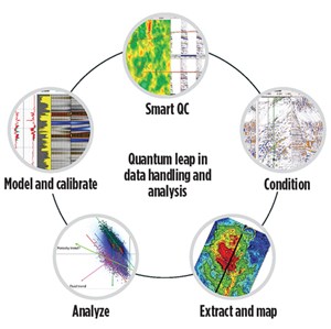
Pre-StackPro software leverages high-performance computing technologies to overcome performance bottlenecks and deliver real-time quantitative interpretation, directly from full-survey pre-stack datasets, Fig. 8. It combines fast processing and advanced data visualization in one tool, giving asset teams the power to QC contractor data, fix data quality problems, and quickly generate angle stacks, attribute volumes, and rich attribute maps in a single interpretation canvas.
Newly acquired seismic surveys continue to grow larger. Seismic wide-azimuth data are available from land surveys, from marine ocean bottom technology, and from multi-streamer and multi-boat surface acquisition. These surveys not only can be 500-fold, but also add a fifth dimension to analyze. These data can be called 5D data, in the sense that in addition to spatial x and y coordinates, recording time and offset, the fifth dimension is azimuth. These datasets require a new visualization method to handle the extra dimension, and benefit from special 5D processing sequences, in addition to standard AVA/AVO techniques.
Sharp Reflections has developed new software, PSPROAzimuthal, designed to work efficiently with these large datasets and to reveal the azimuthal character of the seismic, and of the underlying earth models. This new module views, processes and interprets full 5D gather datasets. Identifying azimuth sectors with increased illumination allows interpreters to better map salt bodies, essential for improving velocity models for sub-salt imaging. PSPROAzimuthal further exploits the pre-stack horizon picker to generate high-quality 5D interpretation, necessary for estimates of azimuthal variation of both amplitude and velocity. Azimuthal variation allows interpreters to evaluate in-situ stress fields, as well as identify areas of aligned fracture zones.
Pre-StackPro offers unprecedented computational speed, excellent scalability, and interactivity on a cloud-ready software platform. Integration of high-quality processing routines and flexible data analysis reduces the need for many different, dedicated “quantitative interpretation” software tools. This reduces cost and cycle time.
Cement evaluation transforms analysis
Wellbore integrity and zonal isolation provided by cement placed between the casing and formation rock are of the utmost importance. Operators rely on the accuracy of cement-bond logs to make critical decisions that can affect long-term well integrity and the environment.
While cement compressive strength has, typically, been used as a key indicator of cement quality, today’s challenging environments require a more detailed assessment. With the capability to generate shear acoustic waves, Baker Hughes’ Integrity eXplorer service provides a new foundation for cement evaluation by responding to the cement shear modulus, which is the true indicator of solid cement behind the casing.
Conventional acoustic-based evaluation techniques may not provide reliable information in the face of some of today’s challenges. The electromagnetic-acoustic transducer technology (Fig. 9) that forms the basis for the service allows operators to directly assess the integrity of cement bonds in any current wellbore fluid environment or cement mixture.
Tortuous wellbores and heavy borehole muds pose potential problems to the acquisition of representative cement evaluation data. The most challenging conditions occur when cement becomes contaminated with borehole mud during the cementing process, or when low-density cement is used. The acoustic impedance of these lightweight, contaminated cements is very low, making them almost invisible to traditional acoustic-based cement evaluation services. The company’s new service incorporates proprietary electromagnetic-acoustic transducer technology to generate a shear acoustic mode to accurately evaluate these types of cements in any current wellbore fluid environment.
The service also eliminates the need for expensive and time-consuming procedures to pressurize the casing for evaluating cement with a suspected microannulus. Evaluation of the cement bond in zones with microannuli is critical for assessing the necessity of remedial cement squeeze jobs. Conventional cement evaluation services perceive a pipe with microannulus as free pipe, even though zonal isolation is achieved. With the help of the acoustic lamb (flexural) mode, the service can detect the presence of a microannulus, and the quality of cement behind it, in a single pass into the wellbore.
Subsea fittings replace orbital welding
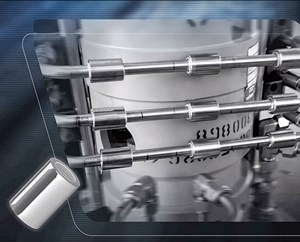
FMC Technologies has developed and patented a technology to replace the orbital welding process that connects small-bore hydraulic tubing used in subsea equipment—the Shape Memory Alloy Subsea Fitting, Fig. 10.
The technology is based on a Shape Memory Alloy, a nickel-titanium material that returns to its original shape after being subjected to environmental changes, such as temperature or pressure. This same material is used widely in the automotive, aerospace and biomedical industries; however, the company is pioneering its application underwater and solving the problems associated with corrosion and susceptibility to hydrogen embrittlement that can occur in a subsea environment.
Shape Memory Alloy connections require only one-third of the cost and time normally needed by welded connections. The fittings are stored in liquid nitrogen and can be installed in only 30 sec. The technology dramatically simplifies and speeds up assembly and inspection times. It is also safer for personnel, since X-ray inspection of welds is no longer needed.
This technology development was done in partnership with Shell Brazil, and it earned FMC Technologies a Spotlight on New Technology Award at OTC Brazil 2015.
HSP reduces subsea output costs
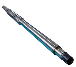
ClydeUnion Pumps, an SPX FLOW brand, offers a hydraulic submersible pump (HSP) designed specifically to provide maximum flexibility and high reliability in subsea wells. The HSP was developed by identifying, and then designing out, the most common failure modes afflicting traditional electric submersible pumps (ESP). The HSP has a life expectancy exceeding 11 years and has demonstrated three times the average mean-time-to-failure compared to ESPs.
The HSP is a hydraulic turbine-driven, multi-phase submersible pump (Fig. 11) that has been applied successfully for 15 years in subsea production wells and is capable of moving 20,000 bpd. Its increased reliability is delivered by a robust hydraulic turbine drive, rather than a downhole electrical power system utilized in ESPs. This minimizes the risk of equipment drive-train failures and eliminates reliance on drive-section seal protectors. The combination of technologies and features creates a protective environment for critical rotor bearing systems, making it possible for the HSP to operate efficiently across a wide performance envelope, a key advantage when optimizing reservoir drainage or addressing changes in well conditions/pump performance.
The HSP is designed to be resistant to wear and corrosion for the life of the well, and delivers high performance in challenging operating conditions, including high viscosity crude and multi-phase fluids. The combination of helico-axial pump stages, with the inherent load following and variable high-speed capability of the turbine drive, enables it to pump continuously to elevated free-gas levels. This enables the HSP to avoid gas-locking by automatically adjusting speed, depending on fluid density. The hydraulic pump also enhances production flow assurance by commingling produced reservoir fluids with exhaust water from the turbine, to provide a low viscosity water continuous flow.
The HSP approximately 60% shorter than an equivalent ESP, minimizing installation time. Its single-shaft design enables the pump to be delivered fully-assembled, easing installation and lowering dependency on skilled personnel during deployment. The result is a downhole pump with higher reliability, which translates into more production uptime while reducing exposure to costly well interventions. This combination makes HSPs the ideal choice for subsea production systems with limited access.
Subsea MUX BOP Control System
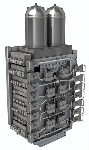
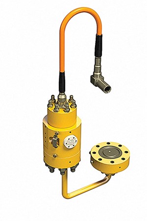
Today, regulations require the availability of two working MUX Control PODs while drilling to provide system redundancy. To satisfy this safety-critical requirement, if a potential POD failure is detected, industry practice is to retrieve and repair the system at the surface, which results in costly downtime. However, imagine a situation in which a BOP control system is smart enough to make required updates or changes to hydraulic functions while remaining subsea. GE is realizing this reality with the new SeaPrime I Subsea MUX BOP Control System, Fig. 12.
This next generation fault-tolerant architecture has the ability to re-configure hydraulic functions subsea, preventing costly stack pulls. Using an ROV to isolate hydraulic functions, the subsea control system can re-route hydraulic functions to targeted redundant sections within the same POD to maintain full operation while subsea. By including a smart redundancy feature, GE has enabled the SeaPrime I system to re-configure itself, offering three times more system availability using just two PODs.
The SeaPrime system has been designed from the ground up using GE’s Design for Reliability (DFR) process, and Reliability Availability Maintainability (RAMs) models, proven in GE's Aviation Nuclear and Power businesses, to drive system design and architecture.
This new design improves maintainability and reduces service costs by simplifying access to critical electrical and hydraulic functions and all serviceable parts. Additionally, eliminating the need to disassemble the POD to access critical functions reduces the opportunity for human error. The SeaPrime I Subsea MUX BOP Control System also eliminates all pilot tubing and connectors—reducing potential leak points by 40%.
The GE SeaPrime I system can be configured for eight-cavity BOP stacks, with 20% spare functions for future growth, allowing drilling contractors to have flexibility in stack configurations today and in the future. This new design offers a solution for both 15k and 20k systems.
Water analysis sensor measures conductivity
AquaWatcher water analysis sensor from OneSubsea, a Schlumberger company, can detect miniscule quantities of water in multi-phase and wet gas flows, and determine the salinity of that water, Fig. 13. Additionally, it can determine the ratio of injected chemicals to water.
The sensor measures the conductivity of produced water at any gas volume fraction (GVF) and most water cuts, including in the transition zone from oil to water-continuous mixtures. Breakthrough of injected water in waterflood applications can be detected at low concentrations, and information about the origin of produced water can be provided, as well. The water property measurements can be used to improve the accuracy of multi-phase meters.
With its patent-pending measurement-based approach, the sensor allows dosage of chemicals to be based on a measurement of the ratio of chemicals to water downstream of the injection, providing substantial risk and cost reduction.
In addition to the significant risk mitigation and reduced costs for chemical injection and reclamation, the sensor allows additional production to be brought online, due to improved utilization of the available injection and reclamation capacity. Other features and benefits include water detection at fractions down to a few parts per million; measurement of water conductivity; calculation of water salinity and ratio of injected chemicals to water; measurements can be sent directly to a subsea control system, a multi-phase flowmeter, or any suitable communications unit; process pressures up to 20,000 psi, temperatures up to 250°F and water depths up to 10,000 ft.
The sensor can be installed stand-alone, or integrated with a multi-phase or wet gas flowmeter. It also can be installed anywhere in a subsea production system, including at the wellhead or in a subsea tree. It uses the reflection of a microwave signal to measure the permittivity and conductivity of the fluid mixture locally. For instance, near the pipe wall in a process pipe. ![]()
- Advancing offshore decarbonization through electrification of FPSOs (March 2024)
- What's new in production (February 2024)
- Subsea technology- Corrosion monitoring: From failure to success (February 2024)
- U.S. operators reduce activity as crude prices plunge (February 2024)
- U.S. producing gas wells increase despite low prices (February 2024)
- U.S. oil and natural gas production hits record highs (February 2024)
- Applying ultra-deep LWD resistivity technology successfully in a SAGD operation (May 2019)
- Adoption of wireless intelligent completions advances (May 2019)
- Majors double down as takeaway crunch eases (April 2019)
- What’s new in well logging and formation evaluation (April 2019)
- Qualification of a 20,000-psi subsea BOP: A collaborative approach (February 2019)
- ConocoPhillips’ Greg Leveille sees rapid trajectory of technical advancement continuing (February 2019)

