Operators achieve photorealistic borehole imaging in oil-based drilling fluids
Drilling a 12¼-in borehole with oil-based mud (OBM) in the Upper Mungaroo formation on Australia’s North West Shelf, an operator needed to characterize reservoir geology and assess economic potential as accurately and expeditiously as possible. Geological objectives included identifying reservoir-quality channel sands and laminations, determining the presence and connectivity of non-channel facies, and calculating the dip and orientation of structural features, such as faults.
Cutting conventional core would have required a lengthy and costly process, and sidewall cores, usually representing only discrete points in the well, would have been of limited use for characterizing formation sedimentology and stratigraphy. Furthermore, the hole was over 4 in. larger than the ideal hole size for which existing OBM-adapted borehole imaging tools had been designed. Legacy imaging technology would have covered a mere 21% of the borehole’s total circumference—too little for geologists to identify a number of key formation characteristics with confidence. Therefore, the operator elected to run a new, high-resolution microresistivity imaging service designed specifically for synthetic- and oil-based drilling fluids.
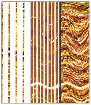
The new OBM-adapted imager achieved an impressive 64% circumferential coverage, even in such a large borehole, more than tripling the coverage of existing technology, Fig. 1. Photorealistic images were sufficient to reveal highly dipping structures, such as natural fractures and faults, depositional features such as cross-bedding and soft sediment deformation, the presence of shales, and the precise location of highly laminated reservoir-quality sandstones. Just as important, the new tool’s unique design enabled the operator to obtain high-definition formation images while running into the hole, despite challenging conditions—eliminating at least one additional logging run, saving offshore rig time and costs, and providing critical information earlier in the formation evaluation program.
This case study illustrates some of the challenges that operators face in seeking to unravel the complexities of today’s conventional and unconventional reservoirs, as well as the value of new high-resolution borehole imaging technology.
NEED FOR HIGHER RESOLUTION
To reliably calculate reserves, maximize production from existing fields, and properly determine where to drill additional wells, oil and gas companies need to dramatically improve their understanding of increasingly complicated reservoirs. To do so, they require highly detailed borehole geological information, such as cores and wireline microresistivity images. These assist in characterizing formation architecture, developing sound reservoir models, and supporting more accurate, timely and informed decisions.
In unconventional reservoirs, for example, geoscientists strive to understand natural fracture networks, including their location and density. They also calculate stresses and predict hydraulic pressures necessary to control and optimize fracture stimulation. In deepwater settings, where the impact of a mistake can be very costly, explorationists must identify many different sedimentary facies and predict their occurrence and trend in the subsurface. Many deepwater formations are thinly laminated beds or channels that require high-resolution techniques to image, analyze, target, drill and complete appropriately. What’s more, deepwater reservoirs typically have very low resistivities—from 1 Ὼ-m in shales to 0.2 Ὼ-m in water-bearing sands. With such small signals, there can be little tolerance for measurement error or noise.
Whole core samples enable geoscientists to differentiate sedimentary facies, but acquiring them can be slow and costly. For this reason, operators usually cut cores only in certain wells and a few important intervals. Without more extensive geological data, reservoir analysis, interpretation and modeling are much less definitive. On the other hand, operators can obtain continuous microelectrical borehole images over an entire open-hole section, or any formation interval, with remarkable simplicity. Until recently, it has been feasible to acquire high-resolution borehole imaging only in electrically conductive water-based muds (WBM). However, high-performance, non-conductive OBMs are being used in the majority of deepwater projects, and a growing percentage of unconventional resource plays.
Over the past decade, new borehole imaging tools adapted for OBM have provided much more technically advanced results than previous OBM-adapted dipmeter technologies. Nevertheless, they still suffer certain restraints. For example, the resolution of OBM spatial imaging falls far short of the quality that WBM tools can achieve. Limited circumferential coverage of the borehole can leave gaps nearly 20% larger than WBM imagers, which must be filled by inference.
Also, to measure reservoir resistivities beyond the barrier created by non-conductive mud, existing OBM imagers depend on fairly complicated physics. As a result, they can generate artifacts that do not represent actual geology, hindering visibility of formation texture. In addition, the electrode layout of traditional OBM borehole imaging tools makes it difficult to detect geologic features that trend almost parallel to the borehole, such as subvertical fractures in a vertical well. Finally, existing borehole imaging tools can only acquire data as they pull out of the hole, due to mechanical design limitations. As a result, stick-and-slip events occur more often, causing noise and further reducing the quality of final images.
Because of these constraints, texture, sedimentology, depositional facies and critical structural features, including the presence and orientation of faults and fractures, often remain uncertain. For years, therefore, operators have needed OBM-adapted borehole imaging technologies with higher definition and borehole coverage, more like existing WBM imaging solutions.
PHOTOREALISTIC IMAGING IN OBMs
Schlumberger recently introduced the Quanta Geo photorealistic reservoir geology service for nonconductive OBM systems. The resolution of its micro-resistivity imaging is as high as leading WBM imagers, while its circumferential coverage is even greater. Field-tested in over 60 wells, it has provided high-resolution images in OBM with oil/water ratios from 60/40 to 90/10, in diverse formations including shales, high-resistivity carbonates and low-resistivity sandstones. A completely new technology has been engineered from the ground up to generate photorealistic images of reservoir geology with core-like detail, covering almost the entire borehole—as much as 98% in 8-in. holes. Due to the sonde’s new design, it can record high-definition image data while running the tool into the hole. No other borehole imaging service today has this unique downlogging capability.
The new OBM-adapted imager has totally digital electronics, which operate at considerably higher frequencies. It also has an innovative mechanical design, new measurement physics, and a larger number of microelectrodes than any borehole imaging technology in the industry—an array of 192 microelectrodes providing geologically representative images of 0.24 in. vertical resolution by 0.13 in. horizontal resolution.
With eight wholly independent double arms and eight imaging pads, the tool is able to sustain good contact with the borehole, even in highly deviated wells, despite changing hole conditions. Since the top and bottom arms operate separately, each pad can rotate 15° around its long axis and alter its pitch angle. If the tool’s position in the borehole becomes eccentered, sophisticated processing algorithms adjust the image data to the proper location. Using spring force to deploy each pad arm independently creates less friction than previous technology. Thus, for the first time, operators can acquire high-definition images while running the tool into the hole. Not only does downlogging save costly rig time, it also reduces the number and intensity of stick-and-slip events and their impact on image quality.
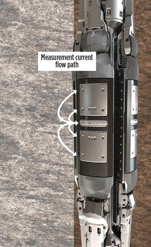
The new OBM-adapted imaging technology also employs new image measurement physics. All microelectrical measurements take place entirely on the pads, so the current flow path is much shorter than conventional WBM borehole imaging tools. An injector at the center of each pad consists of a guard ring electrode surrounding 24 microelectrodes, or buttons. Above and below the injector are large return electrodes. Since there are eight pads, the new OBM-adapted borehole imager has a total of 192 buttons, which is three times greater than previous OBM technology. With a surface area of only 10.8 mm3, each microelectrode is smaller than those used on the most advanced WBM imagers, yielding very high-resolution images.
How does the system work? High-frequency AC voltage between the injector and return electrodes drives a current that flows out of each button, through the oil-based drilling fluid, into the reservoir, and back into the returns, Fig. 2. The optimal operating frequency depends on the resistivity of the formation, so the tool injects a blend of two high frequencies in the megahertz range to cover the appropriate resistivity range. Injected frequencies, three orders of magnitude greater than legacy OBM-adapted technology, effectively minimize the impact of non-conductive mud on resulting measurements. To distinguish the remaining impedance of the mud from that of the formation, specialists apply advanced phase-sensitive signal processing, creating photorealistic images that visualize fine geological features.
The electrode geometry of previous OBM-adapted imaging tools had a tendency to cause greater sensitivity to artifacts, such as desiccation cracks, which often conceal reservoir geology. The new tool’s simpler electrode geometry eradicates these artifacts. With equal sensitivity to both vertical and horizontal features, it can now image fractures that intersect the borehole at any angle. The new OBM-adapted imager can sample formations at a rate of 0.2-in while logging at the maximum speed of 3,600 ft/hr. At 1,800 ft/hr, its sampling rate is 0.1-in., and it can handle formation resistivities with values extending from 0.2 to 20,000 Ὼ-m. With these enhanced capabilities, the new technology offers far more flexibility than existing imaging tools adapted for OBM.
DEEPWATER AND UNCONVENTIONAL PLAYS
Deepwater slope, Gulf of Mexico. Using high-performance synthetic OBM and a 9 7/8-in. bit, an operator in the Gulf of Mexico was drilling deepwater slope deposits. While previous borehole images had differentiated sands from shales with reasonable clarity, the number of depositional facies they could distinguish was limited. Also, few internal structures were visible within thick sandstone units, apart from low-confidence features that appeared to be rip-up clasts. Sedimentological features indicating paleoslope or paleocurrent direction were rarely observed. It was challenging, even to determine structural dip in shales with dehydration cracks. Finally, given the moderate resolution and low circumferential coverage of existing technology, it often proved difficult to visualize natural and drilling-induced fractures at all.
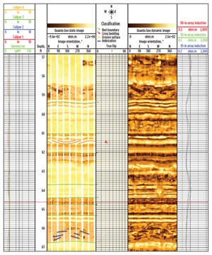
To evaluate the prospect’s economic potential, geoscientists needed to unravel its tectonic features more reliably and distinguish sedimentary facies more precisely.
The operator decided to run the new photorealistic OBM imaging tool, and combine it with an advanced sonic tool. Since the tool design allows downlogging, the operator obtained borehole images while running into the hole and while pulling out, and compared the two. The resolution of images acquired while downlogging was substantially sharper, due to fewer, less intense stick-and-slip incidents. Even in this 97/8-in. borehole, the operator achieved 80% circumferential coverage. A special multi-point statistics (MPS) processing technique was applied to realistically fill in gaps and create full-coverage, photorealistic images.
Even an initial quick-look interpretation of formation images showed more complex structural features than geologists had anticipated, such as unconformities, faults and natural fractures. The presence of nearly vertical, en-echelon fractures on two sides of the wellbore, caused by drilling, enabled them to identify the orientation of maximum horizontal stress. Channel fill and associated facies were visible in considerable detail, in addition to high-energy remobilized shale intervals, and lobe or sheet sands with scours and imbricated shale clasts that clearly indicated paleotransport direction, Fig. 3. Deposits left in-situ from turbidity currents were distinguished carefully from mass transport or slump deposits, which occurred at scales from centimeters to tens of meters. Based on texture and sudden variations in dip, which legacy OBM-adapted imagers would not have detected, the operator identified significant sections of slumped sand, Fig. 4. Traditional borehole images would probably have led interpreters to mistake these sands for channel deposits and erroneously incorporate them in net pay calculations.
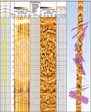
Utica shale, eastern U.S. Using OBM to drill a vertical pilot hole in the Utica shale play, another operator acquired 85 sidewall core plugs throughout two target shale intervals. High-definition borehole images were necessary, both to identify natural fractures and accurately correlate formation evaluation logs with the core samples. Legacy OBM-adapted images would have left large swaths without any borehole coverage, making it unlikely geologists would locate all of the sidewall core holes. In addition, the Utica shale is a thinly laminated reservoir with short, vertical to subvertical fractures, so imaging and correlating fracture traces around the borehole would be no easy task with legacy imagers, since they are not very sensitive to geologic features parallel to the wellbore.
The operator deployed the new high-resolution OBM-adapted imaging tool, which acquired excellent images and covered an impressive 93% of the 8.5-in. borehole circumference, Fig. 5.
The precise locations and geologic context of all 85 core points were imaged successfully. This allowed specialists to correlate laboratory analyses with specific laminae and understand how closely each core sample matched the target zone’s overall reservoir properties. This information facilitated better reserve estimation and improved completion design. Geologists also identified sedimentary structures and stratigraphic details within fluvial sands overlying the target reservoirs, which enhanced their understanding of depositional systems within the basin.
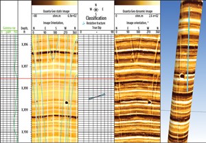
Finally, the new OBM technology effectively revealed near-vertical fractures running almost parallel to this vertical well, indicating that the dominant fracture system in the area strikes NNW–SSW at 80˚–260˚. Subsequent advanced analysis of high-resolution images indicated that where these fractures intersect the wellbore, they are at least partially open. The operator was able to model the opening pressure necessary to reactivate the natural fracture network during hydraulic fracture stimulation.
GEOLOGICAL AND OPERATIONAL VALUE
The resolution and circumferential coverage of borehole images in OBMs today is equal to, and in some ways superior to, that of images acquired in WBMs. With completely re-engineered technology, oil and gas companies operating in challenging environments are effectively reducing risks, avoiding additional logging runs, and minimizing the amount of rig time required to obtain reliable borehole images. The photorealistic quality of these images allows operators to make sense of complicated structure and stratigraphy, construct more detailed reservoir models, place wellbores more confidently, and improve completion designs in both conventional and unconventional projects. ![]()


