Improving underbalanced drilling using air in the Marcellus shale
Underbalanced drilling with air has been popular in the Marcellus and Utica shale plays in the northeastern United States, because of high ROP and reduced formation damage as compared to conventional methods. In 2014, of the 111 rigs drilling in the Marcellus Shale, 27 rigs were drilling underbalanced and 23 were being drilled with air. A unique drilling system, incorporating the use of downhole mud motors, EM MWD, and air hammers, has been specifically designed and ruggedized to address downhole shock and vibrations encountered in air drilling. The use of this system has resulted in significant reduction of non-productive time (NPT) while drilling with air, plus increased ROP and reduced costs.
BACKGROUND
Air drilling provides a significant decrease in hydrostatic pressure over common mud types, resulting in an increased ROP. Additionally, significantly better hole cleaning can be achieved, resulting from the high air velocities used to drill the well. Finally, mud and cuttings handling costs can be reduced since there are no chemicals to absorb and no cuttings cleaning requirements on virgin formation. Early tests of this application proved it as a viable option for the Marcellus and the Utica fields. Initially, hammer bits were used for air drilling, but significant challenges involving directional control emerged as well plan trajectories became more complex. The development of ruggedized mud motors and MWD tools capable of handling these challenges, and the use of specialized fluid control systems eventually allowed for more conventional BHAs to be successful when used for air drilling.
FLUID REGIMES
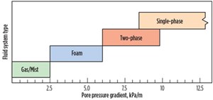
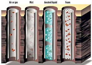
Drilling fluids allow for cooling, lubrication, cuttings removal, and adequate transference of hydraulic energy to the bit and other downhole tools. Though rheology varies, circulation systems focus on operating under specific pressure ranges in relation to formation and reservoir pore pressures. Figure 1 illustrates how various fluid systems are applied over the range of formation pore-pressure gradients.
Overbalanced drilling is the state where the hydrostatic pressure of the fluid column exceeds the pore pressure of the formation. Operating overbalanced is the safest and most common status of a well in typical drilling conditions. The hydrostatic pressure exerted by the mud column functions as the primary well control device. This condition is also the most diverse, as it may be achieved with a variety of fluid types and operating practices with no modifications. Running in an overbalanced condition does, however, allow for some detrimental effects. For example, if the hydrostatic pressure of the drilling fluid exceeds the formation fracture gradient, the operator would need to set casing and continue to drill a smaller hole size. Fluid invasion and formation damage may result in wellbore instability, leading to losses and a possible kick scenario, and may also negatively
affect production.
Managed pressure drilling (MPD) is an adaptive process, where the hydrostatic pressure exerted on the bottom of the hole is engineered for balanced differential pressure. By maintaining drilling fluid pressures that equal the pore pressure of the exposed formation during drilling, operators are able to successfully mitigate some of the detrimental effects found in an overbalanced state such as wellbore instability, lost-circulation zones, over/under-pressurized formations, and shallow flows. These hazards may threaten the operational viability and, ultimately, the economic success of the well. Operations under these conditions report an increased ROP, prolonged bit life, and enhanced drilling efficiency.
Additionally, due to pressures being constantly monitored and manipulated, flexibility is afforded during the drilling process. As formation pore pressure changes from rock to rock, the MPD process allows for successful mitigation and control of bottomhole pressures by using a combination of tools, techniques, and controls that use backpressure, fluid rheology, annular fluid level, circulating friction, and well geometry to attain the desired pressure profile. The MPD methods consist of controlling bottomhole pressure, maintaining a pressurized mud cap, and utilizing returns flow control. Successful implementation may allow for flexibility in the casing design, resulting in the elimination of certain strings, and leading to significant financial savings.
Underbalanced drilling (UBD) is the state, where the hydrostatic pressure exerted by the fluid column is less than the pore pressure of the formation. A simple change of pore pressure or equivalent fluid density may unknowingly transition into underbalanced drilling and represent a kick scenario for an overbalanced system, whereas a constant state of transition exists in MPD systems. However, UBD systems are designed to operate under these circumstances of constant fluid influx from the formation. Since the operational goal is to maintain fluid density below pore pressure, several fluid types
may be utilized.
Two-phase fluid and foam. While many drilling fluid systems are capable of introducing an underbalanced state, intentional lowering of fluid density is typically achieved through aeration. Low-density drilling fluids are broken down coarsely into two-phase or aerated fluids and foams. Aerated fluids are defined by a 46:54 liquid-to-gas percentage ratio. When this ratio is exceeded to 4:96, the drilling fluid is considered foam. The aeration process may utilize compressed air, natural gas, exhaust gas, or cryogenic or membrane nitrogen to relieve the bottomhole pressure.
Nitrogen is typically used due to its low reactivity and lack of combustibility. The introduction of oxygen into an aerated fluid, however, enhances corrosion potential and significantly increases the risk of downhole fires. Aeration may be achieved by an injection unit mixing gas with fluid pumped down the pipe bore via a parasite string concentric casing. Aerated drilling fluid is compressible and significantly attenuates signal from pulse-based MWD/LWD tools, when gas rates reach around 10% of total flow. This situation renders these tools incapable of transmitting adequate data to surface. As such, other telemetry methods are required.
Foam is an aggregation of gas separated by liquid, which may be described as stiff, stable, or Styrofoam. Foams allow for more stable underbalanced circulation system than traditional two-phase systems. They have sufficient viscosity properties, both downhole and at the surface, for successful solids removal. They pose no environmental risk, because they are acid soluble and are not affected by evaporates downhole. Additionally, foam systems have a lower risk of borehole instability due to reduced annular velocities.
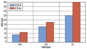
Dry-air drilling, misting or dusting is the use of 100% gas as the drilling fluid system. Air rates in the northeast U.S. typically range from 2,000 to 6,000 scfm. Generally, injection of 5-8 gal per hour of rock oil or hammer oil is used to keep the bit, motor or downhole hammer lubricated and cool. While air drilling requires significantly larger flow velocity for carrying capacity, it significantly increases ROP and bit life. In addition to optimal hole cleaning, decreased costs, and maximum ROP, dusting is able to maintain exceptional shale and clay control. Air is considered to be the least expensive fluid for operations since there is no cleanup or disposal for the fluid on surface. It also drills faster than conventional fluid systems by three to four times, depending on depth and rock strength. Figure 2 shows a comparison of fluid types vs. typical ROP for selected borehole sizes.
Dusting is ideal for hammer operations, but is susceptible to fluid influx from the formation. Once influx has occurred, the fluid must be switched over to a mist or foam. Liquid influx will result in mud rings, which limit hole cleaning and pose a significant risk of pack off or stuck pipe. Under misting conditions, the liquid-to-gas percentage ratio exceeds 4:96. For operations in the northeast U.S., liquid injection rates range from 10 to 50 gpm or higher, and typically incorporate surfactants and corrosion inhibitors. The addition of surfactants prevents the buildup of the mud rings. Corresponding air injection rates range from 1,000 to 5,000 scfm.
Misting has lower velocity requirements than dusting due to liquid carrying capacity. ROP typically slows 30% to 50% in the transition from air to mist due to increased annular pressure. Large liquid influx from the formation would result in rolling back to a foam or two-phase system. As such, the major disadvantages of using air for drilling are 1) limitation in handling fluid influx, 2) reduction of carry capacity compared to foam and other normal mud regimes, and 3) increased flow velocities required to ensure adequate cuttings removal. Figure 3 demonstrates the trade-offs between carry capacity and flow velocities required for select underbalanced
drilling fluids.
WHY USE AN AIR DRILLING SYSTEM?
Dry-air drilling is widely used in the northeast U.S. for top-hole section of wells. The benefits, previously discussed, become compounded as the batch drilling process becomes more commonplace. The reduction in drilling days, drilling fluid costs, and cuttings handling expenses make batch drilling with air economically more viable.
The simplest application of conventional air drilling is used for non-directional applications and involves nothing more than a tri-cone or PDC bit. Other straight-hole or non-directional applications use downhole air hammers or straight-housing air motors. These non-directional assemblies can be run in several different BHA configurations ranging anywhere from a semi-stabilized, fully stabilized or slick configuration. The most common method of straight-hole air drilling is to stack the BHA with additional drill collars to create a heavy vertical hanging effect, that helps maintain a vertical
well bore.
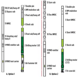
A motorized air-hammer BHA configuration is not as widely used, but is just as effective. This configuration consists of an air hammer positioned at the end of a bent, air motor. This BHA is run with an EM MWD tool and a shock sub. An air bypass sub is used in this configuration to divert a certain percentage of air above the motor to prevent overspinning, Fig. 4a. This added governor aids in hammer control and increases the longevity of a hammer bit. While directional control is possible in this configuration, care must be taken when selecting not only the bit to bend distance, but also the bend angle of the motor. Too much angle does inhibit the flat, striking impact of the hammer and can cause damage to the hammer bit shortening its life. In addition to maintaining a vertical hole, the heavy BHA, mentioned previously, maintains a downward impact of an air hammer to prevent the BHA
from bouncing.
The most common, reliable air directional BHA is a bent-housing air motor with a Tricone bit or PDC bit. This BHA is used with an EM MWD system above the motor with a shock sub below, Fig. 4b.
NEW AIR DRILLING SYSTEM
To mitigate damaging vibration affects, studies were conducted to identify BHA changes and operational practices to improve reliability of the air drilling system. A number of common operational practices were identified as exasperating lateral shocks and vibration. Implemented procedures limited off-bottom rotation, initiated staging compressors, and stopped the practice of drilling off weight-on-bit (WOB).
While differences were seen between BHA configurations, it became best practice to remove all string stabilizers and utilize a ¼-in. under-gauge stabilizer on a bent housing motor with a bend setting no greater than 1.5. Unfortunately, the impact on service reliability was not as substantial as anticipated. As such, a new system was required to withstand these conditions and operate without failures downhole. This upgrade included a modified air drilling motor, a ruggedized EM-MWD tool, a shock sub and, in certain instances, a fluid
bypass sub.
EM MWD. A few operators recognized the potential benefit of drilling with dry air to increase ROP in the area. But, due to congested pads with a great number of wells, the need for directional measurement and control was recognized. Unfortunately, these early adaptors experienced a high number of failures when drilling with MWD and mud motors due to the harsh air drilling environment.
The EM MWD tool was ruggedized, utilizing more robust electronics and alternately-designed shock absorbers to mitigate vibration. The MWD mounting technique was converted to hold the tool in tension, while using redesigned centralizers that allowed other parts of the tool to move with the vibration, instead of trying to eliminate it. The placement of the centralizers was modeled and designed to eliminate drilling harmonics that could damage the MWD tool. The antenna of the EM tool was re-engineered to withstand the high levels of vibration generated by air injection. The overall length was increased by over four times to successfully dampen damaging vibration and prevent concentration on critical parts with small cross sections. The high-rate lithium batteries were extensively lab-tested and then modified to qualify them to drill in this environment.
Motor enhancements. The drilling motor was modified for the air environment by making modifications that reduced the necessary lubrication for the bearing pack. With these changes, the motor only requires oil at 5 gal/hr to extend its operating life. Additionally, a series of self-lubricating dynamic sleeves were incorporated to support side loading, and reinforce the bearing pack, leading to achieve added longevity and better performance.
Shock sub was designed and utilized as a vibration dampener within the BHA. The new design is able to absorb a large quantity of both axial and lateral vibrations generated by the mud motor. The tool successfully dampens high-frequency vibration that induces excessive shock to the MWD electronics and sensors.
Bypass sub. When air hammers are employed, a bypass sub is used to minimize the amount of air pumped through the BHA. This bypass sub helps protect the hammer bits, which are sensitive to the higher air flow rates required for successful hole cleaning.
Once the engineering phase of the project was completed, field trials were initiated. The new system has drilled over 400,000 ft, with a success rate of greater than 98%.
EARLY CASE STUDY
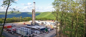
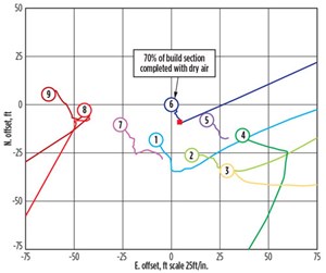
An operator was drilling a series of wells near Washington County in southwestern Pennsylvania. The target reservoir was the Marcellus shale. As this is a populated area, drilling surface locations have to be constructed as small as possible. To make drilling economical, as many wells as possible had to be drilled on a single pad. The case study pad was designed to drill up to nine complex, 3D wells, Fig. 5.
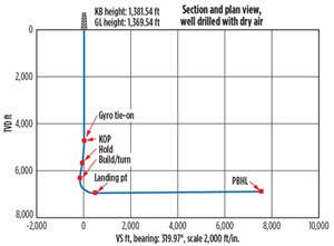
A typical well plan includes drilling from the surface to about 800 ft, and setting 13⅜-in. casing. From surface casing, a hammer bit, without directional measurements, is used to drill to about 4,500 ft. The directional air drilling system is then used to drill from about 4,500 ft to approximately 7,000 ft. Finally, a rotary steerable drilling system is used to drill the curve and lateral. Wells typically reach total depth at about 14,500 ft, Fig. 6.

The first five wells were drilled with a low-angle nudge up to about 30°. The significance of Well 6 is that this well used the directional air drilling system to drill a complex three directional well from 4,600 ft to about 7,200 ft, with an inclination of over 62°, Table 1. Almost 70% of the curve was drilled using the directional air drilling system. This would not have been possible in an air environment without the use of this system. Previously, the customer would have had to use an expensive RSS system to drill this intermediate section. With the RSS, it was also necessary to switch to a fluid based drilling system, which significantly increased mud cost and reduced ROP.
Well 6 was drilled with air at a rate of 3,800 scfm, while injecting 22 gpm of water. The 2,565-ft section was drilled in 34.33 hr. The profile of this well kicked off from 0° at around 4,600 ft MD, built a 30° tangent at a 60°azimuth, and then turned to a 340° azimuth, while building the curve to 62°. Through this section, the MWD tool was able to remain at its lowest power transmission setting, maximizing tool’s battery life and the potential time it can remain downhole. Achieving this amount of build, while drilling with air, cut the time spent drilling the curve to less than 12 hr. The average drilling time to build a curve section, using conventional methods in the Marcellus, takes between 21 and 26 hr. Upcoming drilling plans include the use of the directional air drilling system for Wells 7 through 9. ![]()
ACKNOWLEDGMENT
This article was adapted from SPE 171024, presented at the SPE Eastern Regional Meeting held in Charleston, W. Va., USA, Oct. 21–23, 2014.
- Coiled tubing drilling’s role in the energy transition (March 2024)
- Shale technology: Bayesian variable pressure decline-curve analysis for shale gas wells (March 2024)
- Digital tool kit enhances real-time decision-making to improve drilling efficiency and performance (February 2024)
- E&P outside the U.S. maintains a disciplined pace (February 2024)
- Prices and governmental policies combine to stymie Canadian upstream growth (February 2024)
- U.S. operators reduce activity as crude prices plunge (February 2024)
- Applying ultra-deep LWD resistivity technology successfully in a SAGD operation (May 2019)
- Adoption of wireless intelligent completions advances (May 2019)
- Majors double down as takeaway crunch eases (April 2019)
- What’s new in well logging and formation evaluation (April 2019)
- Qualification of a 20,000-psi subsea BOP: A collaborative approach (February 2019)
- ConocoPhillips’ Greg Leveille sees rapid trajectory of technical advancement continuing (February 2019)

