Limit water cut and gas breakthrough with autonomous inflow control

One of the limiting factors affecting the length of horizontal wells has been the effective management of reservoir sweep with regard to wellbore influx. The added benefit of greater reservoir contact is met with increased differential drawdown across the well length and greater tendency to cut across heterogeneous formation with varying permeability. For many years, inflow control devices (ICDs), which restrict flow by creating additional pressure, have been used to mitigate this problem. They are, however, passive in nature and once installed cannot be adjusted. In the event of water or gas breaking through in an oil well, the disadvantage of the passive ICD become evident as the well would be overtaken quickly by the breaking fluid, since the ICDs are usually designed to choke oil.
Autonomous ICDs (AICDs) are, however, self-regulating and are classed as active. Unlike its passive counterpart, which produces greater choking for higher-density fluids, AICDs choke water and gas more readily. This prevents the well from being flooded when unwanted fluids break through, thereby providing the advantage of being able to even out inflow into the well and choke compartments producing unwanted fluids, leading to greater recovery, lower water cut and gas production.
AICD DESIGN AND OPTIMIZATION
One type of AICD available in the industry uses a levitating disc, Fig. 1. This disc regulates flow based on the fact that a moving stream of fluid will experience a reduction in pressure. The greater the flow velocity, the greater the pressure drop in the stream. If stream velocity above the disc is high enough, the pressure drop generated will lift the disc and restrict the area available for flow. This inevitably chokes the flow. Since the velocity is different for fluids of different viscosities at the same inlet pressures, the AICD chokes fluids of different viscosities differentially.
Improved understanding of AICDs through single- and multi-phase testing has allowed for creation of mathematical models, making it possible to upscale/downscale these devices for changing conditions. The authors have developed a workflow methodology for creation of performance curves for any downhole fluid properties.
A multi-step approach for the design and optimization of an AICD completion design should be followed. First is the collation of customer reservoir data and performance requirements; second is the design of the AICD to suit the reservoir flow characteristics; third is the creation of initial fluid flow performance curves to compare with a passive ICD design; fourth is the generation of AICD performance coefficients for input into linear and non-linear regression simulators; and last is the quality check of the designs regression coefficients for gas control accuracy.
Customer reservoir data required to create an optimum AICD design includes live oil/gas/water densities and viscosities, expected production rates (oil/gas/water) without ICD completion (initial/mid-life/late-life), initial expected drawdown, and well length. These data are input into the design and simulator software design. A unified approach to AICD modelling is paramount, and using the original equation proposed by the early adopters should be a first choice. Most AICD providers are able to provide performance curves, and as such should be able to port into existing or proposed simulation matrices.
MODEL BACKGROUND
Several mathematical equations have been proposed to allow for simulation of AICDs in reservoir simulators. The most popular and widely implemented equation was first proposed by Mathieson et al2, and later, by Halvorsen et al.1 This function is expressed by:
 (1)
(1)
In the equation, aAICD is a user-input ‘strength’ parameter, q is the local volumetric mixture flow rate, and x and y are user-input constants. Parameters ρcal and µcal are calibration density and viscosity, respectively. The mixture density and viscosity are the flowing density and viscosity of the downhole fluids calculated by their volumetric fractions:
 (2)
(2)
 (3)
(3)
Through multiple, full-scale, multi-phase flow experiments, it has been demonstrated that the flow equation (1) may have limited validity past the oil, water and gas boundaries for which it was tested. It is, as such, of paramount importance to develop field-specific coefficients. A more robust and simplified approach is presented in this article. This approach should make it easier to test the benefits of AICDs with most industry-standard reservoir simulators, without any rigorous knowledge about supplier-specific AICD performance.
SIMPLIFIED EQUATION
The calibration density and viscosity were originally proposed to reference the test conditions for which the AICDs were first tested. By setting these to the value of fresh water at standard conditions (µwater = 1cp, ρwater = 1,000 kg/m3), the equation can be simplified to provide a more succinct meaning:
 (4)
(4)
 (5)
(5)
Now it is easier to properly describe AICDs using equation set (5) and by defining aAICD, x and y for fluid conditions across the reservoir.
WORK FLOW
To arrive at field-specific aAICD, x and y, a series of steps needs to be followed:
- Acquire test data for the specific AICD valve, or use any developed mathematical model to present the data in the following format: q (Rm3/day), ρmix (kg/m3), µmix (cp), δP (bar). Table 1 shows the format that any industry-standard regression engine can use. The table lists three independent variables—X1, X2 and X3, and the result, Y.
- Perform multi-variable non-linear regression on the dataset to determine optimum values for aAICD, x and y. Linear regression can also be used by implementing a logarithmic relationship:
 (6)
(6) (7)
(7)
where X1, X2 and X3 are logarithmic expressions of q, ρmix and µmix, and a, b and c are regression coefficients for log(aAICD), y and x. - Provide a simple table for a single-unit AICD, Table 2.
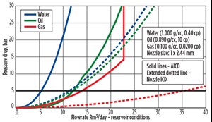
- Compare with passive ICD system. To provide proof of improved recovery, an AICD system should be evaluated against a passive ICD system. As a multitude of passive ICD systems exists in the market place, an equivalent fixed orifice with a discharge coefficient (Cd=0.85) should be used for ease of comparison. Figure 2 shows an AICD vs. passive ICD comparison, where oil flow is matched at a desired pressure differential. In this example, the AICD provides water and gas choking 2-3 times better than a passive device. The net effect of this behavior should be studied over the life of the well. The main challenge for reservoir engineers is to have a meaningful adjustment of the AICD control strength over a simple passive ICD. The best way to optimize this process is to alter the aAICD coefficient by the number of valves used. By simply adjusting both aAICD strength and nozzle diameter, the two systems can be compared in greater detail.
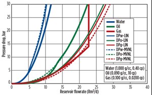
- Quality-check the regression coefficients against test data and choose the best-fit coefficient data set. The regression coefficient set should be chosen, based on which set gives the best fit for the actual field conditions, i.e. water control vs. gas control, or both. Usually, the Multi-Variable Non-linear Regression (MVNL) method is the most rigorous and gives the best overall match. The regression curves should be plotted against real test data and compared for both gas and water control accuracy. In Fig. 3, MVNL coefficients better match the real test data and would be the choice for future simulations.
-
Provide a scalable table of AICD coefficients. If quantity (n) valves are used per AICD joint, equation (5) can be re-written as follows:
 Fig. 3. Comparison between test data (thick lines), linear (LIN) and multi-variable non-linear (MVNL) regression.
 (8)
(8)
A new term aAICD-n is derived, meaning a new aAICD coefficient for n-valves per joint (9)
(9)
Similarly, a new equivalent nozzle diameter can be calculated, based on area, as follows: (10)
(10) (11)
(11) (12)
(12) - A scaled matrix table can now be constructed and used by the production/reservoir engineers to hydraulically optimize the completion, either by using reservoir simulators or steady-state hydraulics software (such as Eclipse/NETool, etc). For more details, please refer to Table 3.
SUCCESSFUL IMPLEMENTATION
The methodology described in this article has been implemented successfully to evaluate autonomous vs. passive ICDs in several large field developments. Some stability problems were reported in the reservoir simulators, and several suggestions have been made on how to improve the stability.
Setting annular flow in the completion annulus to zero, when running the reservoir simulator, seems to improve stability and create results often verifiable by steady-state simulators like NETool. With ICDs or AICDs, annular flow is zero across the reservoir block, such that the error caused by switching off annular flow can be disregarded.
The flowing bottomhole pressure during the life of the well should also be compared to a simple NETool-style steady state simulation, to ensure that the reservoir simulator is, in fact, calculating the pressured drop correctly.
Unless the bottomhole viscosities of oil and water are the same, an AICD should outperform a passive ICD system. Ensuring sufficient hydraulics capacity for total liquids, over the life of the well, is important when running these simulations. It is the authors’ belief that as reservoir engineers become more comfortable with the AICD-coefficients, and with the ability to scale up and down for meeting the required flux rate, there should be a major increase in AICD completions, similar to what the industry has experienced over the last 20 years with the passive ICD systems. ![]()
REFERENCES
- Halvorsen, M., G. Elseth and O. M. Nævdal, “Increased oil production at Troll by autonomous inflow control with RCP valves,” SPE paper 159634, presented at SPE ATCE, San Antonio, Texas, Oct. 8-10, 2012.
- Mathiesan, V., H. Aakre, B. Werswick and G. Elseth, “The autonomous RCP valve—New technology for inflow control on horizontal wells,” SPE paper 145737, presented at the Offshore Europe Oil and Gas Conference, Aberdeen, UK, Sept. 6-8, 2011.
- Krinis, D., D. Hembling, N. Al-Dawood, S. Al-Qatari, S. Simonian and G. Salerno, “Optimizing horizontal well preface in nonuniform pressure environments using passive inflow control devices,” SPE paper 20129, presented at the Offshore Technology Conference, Houston, Texas, May 4-7, 2009.
- What's new in production (February 2024)
- U.S. operators reduce activity as crude prices plunge (February 2024)
- U.S. producing gas wells increase despite low prices (February 2024)
- U.S. oil and natural gas production hits record highs (February 2024)
- Dallas Fed: E&P activity essentially unchanged; optimism wanes as uncertainty jumps (January 2024)
- Enhancing preparedness: The critical role of well control system surveys (December 2023)


