JAMES F. LEA, PL Tech LLC; and HERALD W. WINKLER, Texas Tech University
It has been another banner year for artificial lift innovations. The offerings have been prolific enough, that we have split this year’s report into two halves. This first-half report will cover eight developments in Beam/Rod Pumping, Gas Lift and Gas Well Dewatering.
In beam/rod pumping, a “three-in-one” solution is discussed, whereby coiled tubing is not only used as a pumping string, but as a means for the operator to preventively treat the well. Another item is a downhole sucker rod pump that sets new efficiency standards. Finally, there is a diverter downhole separator, for use in wells where one cannot locate the pump intake below the producing interval.
Among gas well dewatering developments, there is a casing plunger application that improves gas production. A second item is a plunger that provides a complete diagnostic picture of downhole conditions. Yet another device is a low-volume positive displacement pump that is well-suited for dewatering gas and CBM wells, and can be used in a various applications, including severely deviated wells.
As regards gas lift innovations, a single-point gas lift system enhances the effectiveness of wellhead compression. There is also a dual-pocket, side pocket mandrel that is suited for offshore, high-pressure, deepwater and subsea installations. It is designed to lower costs and downtime by improving the pressure integrity of the upper-completion wellbore environment.
BEAM / ROD PUMPING
The trend toward greater emphasis on developing oil versus natural gas continued over the last 12 months. Accordingly, demand for beam and rod pumping-related products increased, resulting in several new innovations.
CT-Three in one solution. The use of coiled tubing (CT) as a pumping string has been proven as a viable solution in artificial lift of fluids in pumping wells. Tests for different applications, such as recovering old wells by converting them into slim holes to be pumped with CT, or dewatering gas wells, proved throughout years of testing that CT is suitable to work as a hollow sucker rod string.
More recently, an innovation from ZEITECS, called the “Three-in-one solution,” presents a new option in the artificial lift field. The idea consists of installing a port at the bottom of the CT string that will allow the field operator to treat the well as a means of preventive maintenance.
The industry is well aware of the troubles caused by sand content, scale and corrosion in rod pumping wells. A stuck pump, caused either by sand or scale, will not only force downtimes but will also require the use of a pulling unit to remove and change the pump more frequently.
This use of the pulling unit is the minimum solution to the problem. A more costly solution, in the case of scale or corrosion, will require pulling and replacement of the production tubing. Bear in mind that when dealing with corrosion, the only possible treatment in a rod pumping well is batch treatment, during which inhibitors are injected or pumped downhole, arbitrarily.
As shown in Fig. 1, using CT as a pumping string, with a port at the bottom end of the string, gives the ability to circulate solvents, inhibitors, hot oil or any fluid suitable to treat the well, all the way to the top of the pump. A suitable preventive maintenance program will avoid, or at the very least minimize, downtimes, extending the life of the downhole pump and tubulars.
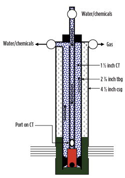 |
| Fig. 1. Using CT as a pumping string, with a port at the bottom end, allows circulation of solvents, inhibitors, hot oil or any fluid suitable for treating the well. |
|
Another advantage of this type of CT application is the ability to produce fluids to surface, either through the CT, or through the annular space between CT and the production tubing, Fig. 2. Applying either case, by means of opening and closing valves on surface, will produce a wash effect, which also prevents premature pump failures and solids settlings.
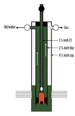 |
| Fig. 2. This type of CT application also allows the ability to produce fluids to the surface, either through the CT or through the annular space between the CT and the production tubing. |
|
New downhole sucker rod pump. Presented by Samson Pump LLC of Keller, Texas, the Samson Pump offers significant advantages over existing pumps. This patented downhole pump can be used, both to produce oil wells and, in particular, to de-water natural gas wells. An efficiency increase of 67%-plus has been shown in controlled research, and in initial field installations, a run-time improvement of tenfold-plus has been demonstrated under certain conditions.
The Pump is fitted with a plunger that is longer than the pump barrel. The plunger always projects out one end of the barrel, thereby forming a variable length seal. This new design significantly increases the surface area between the plunger and barrel (which is considered the seal). The increase in surface area, in turn, reduces leakage. The Samson Pump achieves better efficiency with the increased surface area between the plunger and the barrel. Initial testing/validation results indicate that the API/conventional sucker rod pump of equal bore, with the same clearance (or fit) between the plunger and barrel, and both having the same stroke length, had more than three times the slippage of that of the Samson Pump. The larger seal area also makes significantly greater plunger/barrel clearances possible, if desired, to reduce friction, handle solids, and extend pump run-times without sacrificing relative efficiency.
Another stated advantage of the pump is that sand and other particulates are pulled away (or “washed” with produced fluid) from the space between the plunger and barrel. The particulates no longer accumulate on top of the plunger, as it is pulled upward by the rod string. On the downstroke, the solids are “wiped” off the plunger, as it falls past the seal at the top of the barrel. The “moving seal point” within the barrel of a conventional pump is vulnerable to forced solids between the barrel and the plunger on the upstroke. These solids can accelerate plunger and pump barrel wear, as a result of the solids suspended in the wellbore fluids being swept into the clearance between the plunger and barrel. Some solids can have a higher Rockwell hardness than the components of the pump, and can, therefore, abrade the components during the reciprocating motion of the plunger entirely within the barrel. The frictional heat generated by this wear can also cause the pump components to gall or fuse together. In many cases, when these solids cause the plunger to seize, the barrel may also stick in the tubing. These problems result in frequent pulling jobs and pump repairs.
The Samson Pump has been tested extensively at the Rocky Mountain Oilfield Testing Center in Wyoming and the Red Raider No. 1 test well at Texas Tech University. Furthermore, field installations in the Eagle Ford shale, Hosston formation, Permian basin, and others, have verified the performance claims stated here. Samson Pump has also been awarded two grants from the U.S. Department of Energy, plus a RPSEA (Research Partnership to Secure Energy for America) Energy Award. One way to cut costs, due to sand problems, is to raise the pumps up the wellbore to lessen the amount of solids handled by the pumps. However, the ability to lower the Samson Pump and produce from the pay zone, and still handle solids as claimed here, may allow the possibility of more drawdown in solids from producing wells.
Downhole diverter gas separator. The Diverter Downhole Separator is designed to be used in wells where it is not possible to locate the pump intake below the producing interval. Increasing liquid capacity and gas separation capacity over conventional poor boy or improved, collar-sized, downhole gas separators is the mission of the Downhole Diverter Gas Separator. The increased separation capacity of this device from Echometer Co. is provided by using the larger tubing-casing annulus for both gas separation and liquid separation, Fig. 3. A simple movable rubber seal is used to divert the flow of liquids and gas vertically from below the rubber seal through a central tube approximately 5 ft in length.
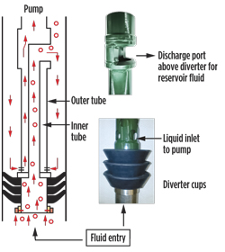 |
| Fig. 3. Schematic diagram of the Downhole Diverter Gas Separator and its components. |
|
When the fluids exhaust into the tubing-casing annulus above the seal, the large annulus flow area reduces the annular gas velocity, which allows the liquid to fall back through the large area tubing-casing annulus into the pump intake. The larger tubing-casing annular area below the diverter exhaust port provides high liquid capacity. The large tubing-casing annular area above the diverter exhaust port reduces the gas velocity, reduces liquid hold-up and provides high gas separation capacity.
Often times, top hold-down pumps are used, when debris and/or sand are present in the well. Some of the gas separators used with top hold-down pumps are inefficient. Often, a perforated sub is placed immediately below the seating nipple, and a joint of tubing that extends below the seating nipple acts as the outer barrel of the gas separator. The area between the ID of the joint of tubing and the OD of the pump is often very limited, and the gas separation process is inefficient.
The Diverter Gas Separator is suited for use with the top hold-down pump by installing a tubing anchor at the bottom of the tubing string, then below the tubing anchor is the seating nipple, then a joint of tubing, then the diverter gas separator at the bottom. The top hold-down pump will extend down into the joint below the seating nipple, and relatively gas-free liquid will flow from the top of the Diverter Gas Separator upward a few feet into the inlet of the pump. When the liquid is in the conduit to the pump inlet, the pressure drop should be minimized, because released gas, due to a pressure drop, will be forced into the pump and will reduce pump chamber liquid fillage.
This separator design was developed with the objective of achieving the same efficiency and flowrate capacity that could be obtained, if it were possible to locate the pump intake below the entry point of free gas into the wellbore. The separator described here is designed to be used in wells, where it is not possible to locate the pump intake below the producing interval. The overall performance of this separator is similar to that of a natural separator.
The new separator overcomes the disadvantages inherent in the packer type separator, by maintaining the full area of the casing annulus through elimination of the external riser pipe, routing the fluid flow within the tool. It also previous disadvantages by eliminating the mechanical elements of the hook wall packer, to facilitate the installation and removal of the assembly.
At the time of drafting this report, Echometer Co. was planning, with the assistance of several oilfield operators, to undertake field tests of the Diverter Gas Separators in a variety of vertical and directional wells.
GAS WELL DEWATERING
The emphasis on plunger lift as the preferred method for dewatering gas wells continues. But poking its head up among the plungers is a low-volume pump that is proving its worth for gas and CBM wells.
ProOp Plunger provides diagnostics. NOV’s Monoflo ProOp Plunger technology is delivering field results that are re-defining production economics and operational efficiency for plunger lift wells. This plunger is a technologically advanced tool that records data and delivers complete diagnostic “pictures” of downhole conditions that have never been seen before. During each cycle, the ProOp Plunger captures data with its collar locator and on-board sensors, Fig. 4. These data include accurate plunger velocities, fluid levels, auto collar count, tubing holes, operational interference and production effects from compression. Using its advanced software program, the diagnostic “pictures” can be quickly uploaded and scanned for problems with operations or well behavior, which allows operators to proactively manage their reservoirs, evaluate well performance, improve well operations, increase well production, reduce operating costs and boost profitability. The system is also user-friendly, and instant analysis can be done on-site by downloading the data directly to a laptop.
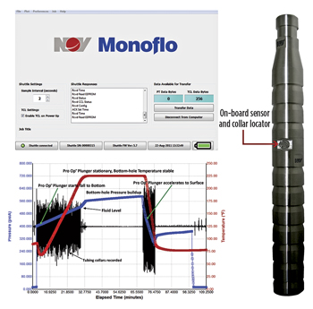 |
| Fig. 4. The ProOp plunger provides a complete diagnostic picture of downhole conditions. |
|
Low Volume pump handles dewatering efficiently. Weatherford has a long history of developing and operating hydraulic piston and jet pumps. The company has recently released a positive displacement pump that it says will never gas lock, even when pumping 100% gas. This pump is ideal for dewatering gas and CBM wells, and can be used in a variety of applications, including severely deviated wells.
The Low Volume (LV) pump (Fig. 5) can produce from 10 to 50 blpd. It is functional to 10,000 ft and uses less than 5 hp at the surface for volumes up to 25 bpd. It uses a field-proven engine end, plus a field-proven reversing valve, and can operate at speeds down to 4 spm at 10,000 ft.
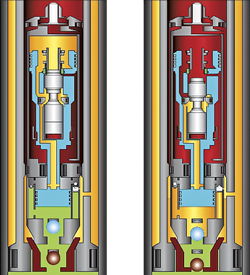 |
| Fig. 5. The LV pump is ideal for dewatering gas and CBM wells, and can be used in a variety of applications. |
|
Multiple month-long field tests have shown marked increases in gas rate production using the LV Pump to remove liquids from wellbores. Field tests have been done in eastern Oklahoma and West Texas.
The pump has done much better than anticipated in deliquifying the eastern Oklahoma well. The well was previously unloading, using a plunger lift system, but with the adoption of the new LV pump, the production of liquids from the well increased from 15-20 bpd to 40-50 bpd. Gas production has increased from 15-20 Mcfd to more than 200 Mcfd.
The goal for the West Texas well was to reduce electricity demand while maintaining production rates. The local power grid operates at or near its limit, and no additional wells can go online. The LV pump consumes only 60 kw/day, while a rod pump system in a companion well nearby consumes 131 kw/day, a reduction of 52%.
The free-style pump is installed with the power fluid, while the fixed-style is attached to the tubing and is installed along with the tubing. As of now, the smallest casing for which this pump can be installed is 5 ½ in.-23#. A design is available for 4 ½-in. casing, but it is being held in reserve until field testing is completed.
Casing plunger applications. PAAL LLC recently took a new look at the old problem of removing fluids from gas wells, challenging the conventional wisdom of decades of efforts. Accordingly, the firm designed and patented an innovative plunger, using mechanical and pneumatic features to actuate flexible-diameter sealing cups at the bottom of the wellbore, Fig. 6. This design has been tested successfully in more than 50 wells, representing widespread applications. The departure from fixed-diameter cups, with frequent failures, has re-opened the door for improving gas production by removing wellbore fluids using casing plungers.
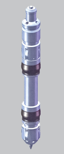 |
| Fig. 6. The PAL Plunger, uses mechanical and pneumatic features to actuate flexible-diameter sealing cups at the bottom of the wellbore. |
|
Building on the success of flexible diameter sealing cups, engineers developed another breakthrough to remove fluids from the lower perforated intervals in multiple-zone completions. This patented innovation, the PAL Plunger/Hybrid, offers the possibility of removing fluids from the entire perforated interval in vertical wells, Fig. 7. It also opens the door for success in coalbed methane (CBM) and horizontal wells, as gas production rates decline and fluid loading adversely restricts gas output.
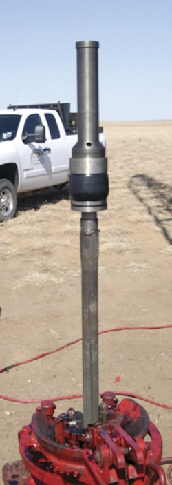 |
| Fig. 7. The PAL Plunger/Hybrid is another technological breakthrough that removes fluids from the lower perforated intervals in multiple-zone completions. |
|
PAL Plungers developed a simple hybrid concept that employs a wireline-set packer element/assembly above the top perforation in vertical wellbores that includes a smaller-diameter tubing velocity string extending into the lower perforations. The wireline-set packer contains a ball and seat to hold lifted fluids at the packer. The velocity string lifts the fluid from the lower perforations by maintaining a sufficient critical, or entrainment, velocity to lift the fluids to the packer element. The accumulated fluid is then lifted to the surface on the next cycle of the PAL Plunger/Hybrid.
Field testing over a three-year period proved that the fluid is removed from the lower perforations and the wellbore, resulting in a gas gradient over the velocity string tubing section below the packing element that is less than the gas gradient in the uppermost wellbore sections. Removing essentially all the fluids from the perforated intervals and eliminating the buildup, or loading, of produced fluids provides the optimum conditions for maximum gas production and extension of the well’s productive life.
The old historical design concept employed a fixed-diameter sealing cup that remained in constant frictional contact with the casing wall from the top of the casing string to its bottom. The fixed-diameter sealing cup was selected to match a single inside diameter of casing and relied on falling to the stop located in the casing above the top perforation. Many wellbore variations and conditions prohibited the successful fall of the casing plunger and resulted in frequent failures that required mechanical retrieval. As cup wear occurred through normal operations, no mechanism existed to extend the life of the cup, and replacement was the only option.
GAS LIFT
Recent innovations include a mandrel ideally suited for offshore situations, and a single-point gas lift system that enhances wellhead compression.
Barrier Series dual-pocket, side pocket mandrel. Suited for offshore, high-pressure, deepwater and subsea installations, the Barrier Series systems from Schlumberger’s Camco unit are designed to lower costs and downtime by improving the pressure integrity of the upper-completion wellbore environment. The dual-pocket, side pocket mandrel (Fig. 8) is based on an existing Camco dual-pocket, side pocket configuration with a dual- inline, redundant, leak-tight seal. This configuration allows for the use of two separate, distinctly retrievable flow control check valve devices that work independently to simultaneously meet flow control and pressure barrier system requirements.
 |
| Fig. 8. The Barrier Series dual-pocket, side pocket mandrel prevents communication between the tubing and casing. |
|
The Barrier Series mandrel is a round-body, fully machined mandrel, with a one-piece, twin 1½-in. bore pocket design, plus a dual-tool discriminator containing a tubing-to-casing barrier valve (TCBV). The valve prevents communication between the tubing and casing, when the normal operating gas lift valve is removed from the primary pocket. A 1 1/2-in. TCBV barrier valve, along with a standard Barrier Series valve, enables well unloading. Multiple models of the Barrier Series gas lift valve and traditional Barrier Series orifice valves facilitate continuous-flow lift operations.
Both the integral tubing and casing barrier valve and active gas lift valves are slickline retrievable. This new technology incorporates dual, flush-mount, full-length OD grooves to facilitate cable and control-line bypass, reducing overall running OD and offering maximum line protection.
Velocity Lift (single-point gas lift). “Velocity Lift” is a (patent-pending) single-point gas lift system from Cyclone Production Tools. It enhances the effectiveness of wellhead compression used for artificial lift in wells with no tubing. The system is deployed on a concentric (tube-in-tube) coiled tubing string inside the casing, and is landed at or near the perforations, Fig. 9. Wellbore fluids enter through the bottom portion of the tool and are trapped by the internal Standing Valve (SV). The trapped fluids are then lifted to surface up the production tube (inner) via an injection gas rate, at or above Critical Velocity (CV). This closed-loop system utilizes Cyclone’s patented Choke Sleeve Technology, which creates a Venturi effect in the tool. This Venturi effect, along with the reduced friction pressure from the smooth bore tube, reduces the injection rate needed for maintaining critical velocity. In the event that injection gas is interrupted, fluids in the production tube fall to the bottom, and the hydrostatic fluid weight closes the SV in the tool. The fluid is then trapped in the system and ready for injection gas to be applied again.
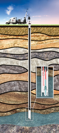 |
| Fig. 9. Schematic of Velocity Lift system. |
|
The system’s capabilities were proven in a case history in Oklahoma. In the example, the Rowe Coal well in Tulsa County, there was produced water, as measured from a weekly well test. The rods, pump and tubing were pulled from this well, and the Velocity Lift System was installed Dec. 15, 2010. The Velocity Lift tool was landed at 1,410 ft. The system was plumbed in and operational within a couple of hours.
Gas from the compressor was injected at 400 to 600 psi. At one point, the well began to make 250 bwpd, mainly through the 4 ½-in. annulus. On several occasions, the check valve hung open from coal fines, which allowed supply gas to come up the annulus. This was resolved by reversing flow and forcing the ball shut from the suspended coal fines. It was felt that the 110-psi discharge pressure was restricting flow. In mid-April, 2011, this was corrected by re-plumbing the system and setting an auxiliary disposal pump. Discharge pressure was lowered to 35 psi, and water rate increased to 150 bpd.
COMING NEXT MONTH
Part 2, the final installment of this report, will cover an even greater number of artificial lift developments in the categories of ESPs/Downhole Pumps; Chemical and Injection Pumps; and Measurement/Surveillance devices. 
|
AUTHORS
|
 |
JAMES F. LEA teaches courses in artificial lift and production for Petroskills. He holds BS and MS degrees in mechanical engineering from the University of Arkansas and a PhD from Southern Methodist University. He worked for Sun Oil as a research engineer from 1970 to 1975, taught at the University of Arkansas from 1975 to 1978, was team leader of production optimization and artificial lift at Amoco EPTG from 1979 to 1999 and was chairman of Texas Tech University’s petroleum engineering department from 1999 to 2006. |
|
 |
HERALD W. WINKLER is former chairman and now a professor emeritus and research associate in Texas Tech University’s petroleum engineering department located in Lubbock, Texas. He also works as a consultant to the oil and gas industry in artificial lift, specializing in gas lift. |
|


