JOHN L. KENNEDY, 21st Century Energy Advisors Inc.
Since drilling rigs were installed on wharfs extending a few hundred feet over the water more than a century ago, petroleum has been produced from beneath the ocean. Today’s sophisticated drilling and production equipment, and innovative engineering and construction techniques, repeatedly make offshore operations routine that once seemed impossible. Still, new ideas continue to emerge to push offshore petroleum operating frontiers farther, cut costs and increase recovery.
And projects to exploit non-hydrocarbon energy sources are appearing on the offshore engineering and construction scene as well. Renewables are off to a modest start, to be sure. BP forecasts that between 2008 and 2035, their share of total energy demand will grow from 7% to 14%. But renewables are getting increasing attention and capital as the diversification of the world’s energy supply marches on.
PETROLEUM’S FOCUS
Innovation in offshore oil and gas facilities today has much to do with monetizing natural gas reserves and designing structures to safely exploit the petroleum potential of Arctic waters. And across an expanding spectrum of applications, moving more production operations from the water’s surface to the ocean floor is boosting recovery and field life, and minimizing the industry’s environmental footprint.
Tweaking existing concepts. As new offshore drilling and production solutions are field proven, classic platform and rig designs continue to evolve as specific applications call for special features.
A deepwater dry tree unit designed for Brazil’s Papa Terra development was awarded last year to FloaTEC, the 50/50 joint venture between McDermott International and Keppel FELS, to deliver deepwater floating production systems. First oil is expected in about three years.
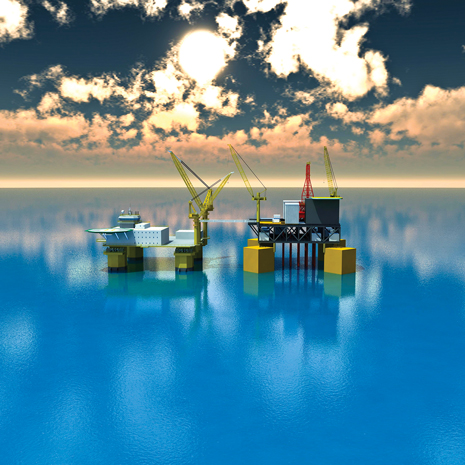
An evolution of the classic TLP design, the extended tension-leg platform (ETLP) will be installed in about 3,870 ft of water in the Campos basin field, according to FloaTEC, Fig. 1. Petrobras (62.5%) is operator of Papa Terra; Chevron (37.5%) is a joint venture partner.
The Big Foot TLP for the Gulf of Mexico will be the deepest TLP when installed, according to FloaTEC. The company was awarded the detail engineering work late last year after the project was sanctioned in December. The structure will be located in Walker Ridge block 29, where water depth is 5,187 ft.
Project partners are operator Chevron (60%), Statoil (27.5%) and Japanese trading firm Marubeni (12.5%).
 |
|
Fig. 1. An extended tension-leg platform will be installed in 3,870 ft of water in Brazil’s Campos basin. Image courtesy of FloaTEC.
|
|
.jpg) |
|
Fig. 2. The first deployment of Shell’s floating LNG design will be for the Prelude project off the northwest coast of Australia. Image courtesy of Shell.
|
|
For Chevron’s Wheatstone project offshore northwest Australia, Technip has designed a steel gravity-based platform, Brian Roberts, Technip’s general manager of business development for offshore facilities, told World Oil. The self-installing rectangular base has four columns that will support topsides weighing 35,000 metric tons, one of the heaviest yet to be installed by the float-over method. In this process, the base is installed, then a barge carrying the topsides is winched between the columns, and the topsides are lowered into place. Because the field is in a cyclone-prone location, the topsides will be at a height of 26 m above the ocean surface.
Kiewit-Aker Contractors—a 50/50 joint venture between Peter Kiewit Infrastructure and Aker Solutions ASA—has a front-end engineering and design (FEED) contract with ExxonMobil Canada Properties for a gravity-based structure to be deployed at the Hebron project offshore Newfoundland and Labrador in about 300 ft of water. Hebron is estimated to contain 400–700 million bbl of recoverable heavy oil. First oil could be produced before the end of 2017.
According to Aker Solutions, the Ichthys project off northwestern Australia is “an example of the state of the art of deepwater production.” Initial capacity of Ichthys, a joint venture between Inpex Browse Ltd. and Total E&P Australia, will be more than 8 million metric tons per annum (mtpa) of LNG, 1.6 million mtpa of LPG and 100,000 bpd of condensate. Water and condensate will be removed offshore, then the gas will go to onshore processing facilities in Darwin via an 885-km subsea pipeline. A final investment decision is set for fourth-quarter 2011; construction could begin in early 2012, according to Inpex information.
Liquefaction and gasification. Shell Australia received environmental approval late last year to use the floating LNG concept to develop its Prelude project gas fields off the northwest coast of Australia, the first deployment of the company’s FLNG technology, Fig. 2. It also will be used to develop the Greater Sunrise gas fields in the Timor Sea, expected to produce around 4.0 mtpa of LNG and condensate.
Floating LNG technology can eliminate the need for offshore compression platforms, long pipelines to shore, near-shore works such as dredging and jetty construction, and onshore development. An FLNG facility can also be redeployed to another gas field.
Technip, in a consortium with Daewoo Shipbuilding & Marine Engineering, has been awarded a FEED contract for a 1-mtpa FLNG unit by Malaysia’s Petroleum Nasional Berhad (Petronas). The contract will be completed in the second half of this year. Technip also has its own design for a 2-mtpa FLNG vessel.
Aker Solutions delivered the first offshore LNG regasification terminal in shallow water in the Adriatic Sea. The project offshore Rovigno, Italy, installed in 2009, receives LNG primarily from Qatar, stores the LNG, then regasifies it and sends it through a 17-km pipeline to the Italian gas distribution system onshore.
With the prospect of a proliferation of FLNG projects, classification society Bureau Veritas early this year issued a set of rules for offshore floating gas units. The comprehensive rules cover everything from structure design principles to the cargo containment system, to piping and electrical, to swivels.
For smaller gas reserves. LNG projects require large reserves and matching markets to be cost-effective. A compressed natural gas (CNG) scheme can make smaller reserves profitable and speed development.
Whether LNG or CNG is the best choice depends on the project. According to information from EnerSea Transport LLC, the economics of LNG will be more favorable than those of CNG at a transportation distance of about 2,500 km, assuming a very large reservoir (3–5 Tcf or more) and correspondingly large gas flowrates.
A CNG system is scalable, redeployable and independent of water depth. It can be applied in Arctic areas that have iceberg exposure, and can overcome cross-border issues that might prevent construction of a pipeline, according to EnerSea. The company has developed preliminary designs for CNG ships with capacities from 70 MMcf to 1 Bcf.
Subsea factories. Statoil’s Snøhvit LNG project in the Barents Sea, where the “platform” is on the seabed, is one approach to dealing with hostile environments. But the benefits of moving production operations—oil boosting, gas compression, separation—to the ocean floor are not limited to the most extreme environments.
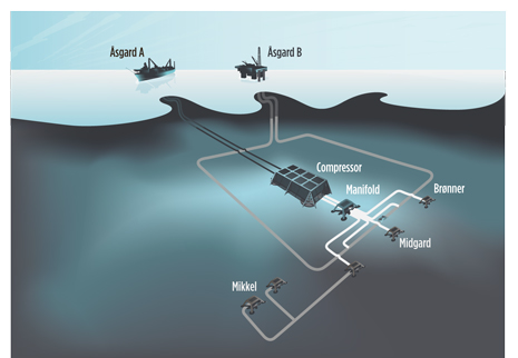
Statoil ASA will install subsea gas compression facilities in Åsgard field to help recover the field’s large remaining reserves, Siri Espedal Kindem, Senior Vice President, Technology, told World Oil, Fig. 3.
 |
|
Fig. 3. Subsea compression at Statoil’s Åsgard field will help recover the field’s large remaining reserves. Image courtesy of Statoil.
|
|
 |
|
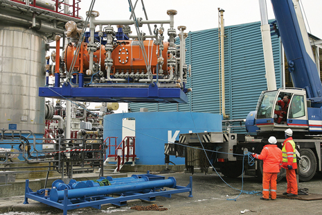
Fig. 4. A subsea compressor was installed for testing in 2008 at Statoil’s Kårstø Laboratory in western Norway. Image courtesy of Kåre Spanne/Statoil.
|
|
“Compressing gas [with] subsea installations represents a considerable technological leap for the industry,” said Kindem. “Our effort to verify subsea compression systems for the Åsgard field at our K-lab facilities paves the way for future subsea-to-shore solutions in combination with subsea processing.”
The Åsgard A oil production ship will supply electricity to power a motor that drives the subsea compressor, Fig. 4.
At its Tordis field, Statoil installed the first complete subsea solution for separating and injecting water and sand from the wellstream; for Tyrihans field, the company developed the first subsea raw seawater injection facility, Kindem said.
“Subsea compression is our next step toward a ‘subsea factory,’” she said.
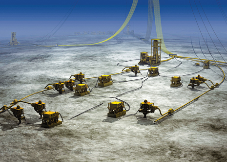
Scheduled for first oil in the second half of this year, Total’s Pazflor field offshore Angola has three 1,200-metric-ton subsea separation units at a depth of more than 2,600 ft, Fig. 5. After separation, oil and water will be pumped to the surface; gas will rise to the FPSO.
Anticipating Arctic challenges. Some existing facility designs can be adapted to Arctic waters, but offshore structure design criteria for the Arctic differ markedly depending on water depth.
Artificial islands have already proven practical for shallow water. Sophisticated modeling tools offer improved design solutions for problems involving ice scour, ice loading on subsea and surface structures, permafrost degradation and frost heave, according to Technip.
These modeling tools can simulate ice flow past a structure and help predict ice movements, Roberts said. He added that this capability and other technology would allow Technip to migrate its experience with artificial islands in the Middle East into Arctic region designs for shallow water.
Another proposed approach is an island made of prefabricated barges, fitted with appropriate topsides, towed to the field site and held in place with piles. An inclined perimeter would break ice and reinforce the hull. PND Engineers Vice President Kenton Braun described the concept in a presentation at February’s Arctic Technology Conference (ATC) in Houston.
He said the concept could be applicable in water depths of 15–35 m. In less than 15 m, a gravel island would be more economical; in more than 35 m, the piles needed for this design would be too long to be practical. An island measuring 200 m square, composed of four barges, would require about 180 piles of 48 in. each, Braun said.
Attention is also focused on ways to protect subsea wellheads and equipment from iceberg scour. Concepts being tested include a truncated cone and a subsea protection “box” that would house subsea equipment, according to a presentation at ATC by Arash Zakeri, director of geotechnical engineering for C-Core.
For deep Arctic water, floating structures will also evolve from current concepts, at least for now, Technip’s Roberts told World Oil. For example, Technip designed its Arctic spar based on a conventional spar, but with a special conical section at the water’s surface designed to break sheet ice and ice ridges. A sloped section forces ice downward toward a section of smaller diameter that offers less resistance to ice forces.
“It is designed to withstand strong ice forces,” Roberts said. “But it also must be capable of being disconnected and towed to safety if those forces become too great, or an iceberg poses a danger.” The decision to disconnect would be based primarily on mooring line tension forces, or the detection of a large iceberg threat. The Arctic spar would reduce reliance on ice management and host 20–30 wells. No Arctic spars have yet been built, but Roberts says Technip’s design is ready to go to the shipyard.
 |
|
Fig. 5. Total’s Pazflor field offshore Angola has three 1,200-metic-ton subsea separation units at a depth of more than 2,600 ft. Image courtesy of FMC Technologies.
|
|
 |
|
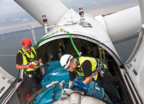
Fig. 6. A service team works atop a 2.3-MW wind turbine at Sweden's Lillgrund offshore wind farm. Image courtesy of Siemens.
|
|
At the ATC, Nicolas Pilisi, technology development engineer for Blade Energy Partners, outlined other options for deepwater Arctic production. Passive designs such as fixed structures that would need to resist ice sheets and ridge loads are not technically and economically feasible, he said.
Existing options for year-round operation with first-year and multiyear ice include a winterized ice-breaker drilling vessel; for operation in open water season, a winterized semisubmersible could handle first-year ice. An icebreaker drilling vessel for deep water could cost in the range of $500 million.
New concepts include two winterized circular non-ship-shaped drilling vessels. One, with a cylindrical hull, could handle first-year ice; another, with a sloped hull to break ice and a reduced diameter at the water surface, could also handle multiyear ice, according to Pilisi.
Russia’s Shtokman natural gas field in the Barents Sea will have the first floating platform to operate in ice conditions. A subsea production system will be tied back to the disconnectable, ice-resistant ship-shaped floating platform about 550 km from shore.
With the growing interest in Arctic exploration and development by the several countries around the pole, harmonization of standards is an important objective. A step in that direction is the International Organization for Standardization’s recently released standard ISO 19906, which provides recommendations and guidance for the design, construction, transportation, installation and removal of offshore structures in Arctic and cold regions that are subject to sea ice, icebergs and icing conditions. Approved in December, it is expected to be adopted by most, if not all, countries, and by all companies.
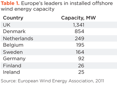
| TABLE 1. Europe’s leaders in installed offshore wind energy capacity |
 |
 |
|
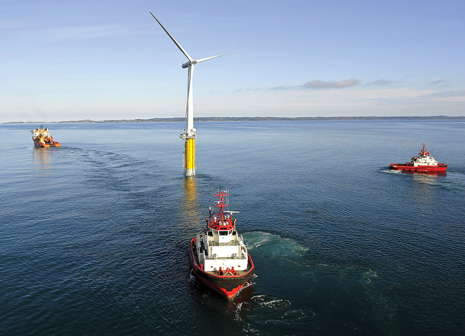
Fig. 7. The world’s first large-scale floating wind turbine, 12 km southeast of Karmøy in Norway, is installed in 220 m of water. Image courtesy of Statoil.
|
|
 |
|
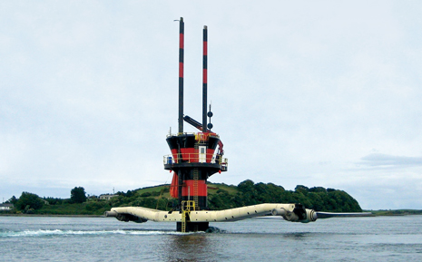
Fig. 8. The SeaGen prototype uses twin 16-m-diameter tidal-wave-driven rotors to generate 1.2 MW at a current velocity of 2.4 m/s. Image courtesy of Marine Current Turbines.
|
|
WIND AND WAVE TO WIRE
Among renewable offshore energy resources, wind is the most technologically and commercially advanced, Table 1. Ideas for turning ocean wave action into usable power are in an earlier stage. And furthest from commercialization is ocean thermal energy conversion (OTEC), which uses seawater temperature gradients to drive electrical turbines.
Europe: Wind epicenter. According to a January report by the European Wind Energy Association, 308 new offshore wind turbines totaling 883 MW were fully grid connected in European nations during 2010, a 51% increase on the previous year. By the end of last year, 1,136 offshore turbines had been grid connected, totaling 2,946 MW in 45 wind farms in nine European countries, according to the report, Fig. 6.
Siemens AG installed the world’s first offshore wind farm in Vindeby, Denmark, in 1991. “Until now, we have sold 1,366 wind turbines and have an order backlog of more than €6 billion in offshore alone,” Gustl-Bernhard Friedl, head of offshore for the company’s wind power business unit, told World Oil. “We see huge potential for offshore wind energy … particularly in Europe and China.”
The company’s direct-drive turbines and its Hywind project provide “a solid foundation for our future activities in the wind industry,” Friedl said. The Hywind project, installed in 2009 in 220 m of water off the west coast of Norway with a 2.3-MW Siemens turbine, is the first floating wind turbine in the megawatt range, Fig. 7.
The fundamental questions related to the floating wind turbine concept have been answered, according to Siemens. But foundation, electrical infrastructures and installation methods still need fine-tuning.
Completion of Siemens’ 140-turbine offshore wind power plant 25 km off the coast of Suffolk in the UK is set for 2012. The plant, called Greater Gabbard, will have an overall capacity of 504 MW.
Construction is set to begin late this year on the 175 Siemens SWT-3.6 turbines for the London Array offshore wind project, owned by Dong Energy, E.ON UK and the Abu Dhabi Future Energy Company (Masdar). It will be the largest offshore wind farm to date, with a first-phase capacity of 630 MW.
Forewind—a consortium of Statoil, renewable energy group Statkraft Energi AS, Scottish and Southern Energy (SSE) and German utility RWE AG—will decide in 2014 whether to develop the Dogger Bank wind farm in less than 30 m of water in the UK North Sea. Both Statoil and Statkraft are also involved in developing the 315-MW Sheringham Shoal offshore wind farm in the UK, due onstream this year.
.jpg) |
|
Fig. 9. Wave Hub was installed late last year off southwest England for large-scale testing of wave energy technologies. Image courtesy of Wave Hub/Deborah Clark Associates.
|
|
.jpg) |
|
Fig. 10. An artist’s conception shows the Oceanlinx tidal array, which uses an oscillating water column design to capture wave energy. Image courtesy of Oceanlinx.
|
|
Centrica Energy’s 270-MW Lincs offshore wind farm, located 8 km off the Lincolnshire coast, received final investment approval late last year. The £750 million project will deliver first power in 2012.
“The offshore wind industry needs to reduce cost dramatically over the next five to 10 years,” Per Bull Haugsøen, managing director of OWEC Tower, told World Oil. “We believe an integrated approach is essential [to achieving that goal].”
The company’s OWEC Jacket Quattropod (OJQ), a substructure including a tubular tower, middle section and jacket foundation with piles, could reduce weight by 30–50% compared with commonly used technology, according to the company.
US: Cape Wind. The American Wind Energy Association's January market report cited three developers with power purchase agreements for US offshore wind—NRG Bluewater Wind for its Mid-Atlantic Wind Park, Deepwater Wind for its Block Island Wind Farm, and the Cape Wind project.
Cape Wind received final approval from the US Department of the Interior in April 2010. The 130-turbine offshore wind farm on Horseshoe Shoal in Nantucket Sound will connect to the electric grid at Yarmouth, Massachusetts. Construction is expected to take about 18 months.
Waves and tides. Coastal regions with strong tidal currents such as those in the UK, Ireland, Canada, France and East Asia are potential energy sources.
Marine Current Turbines Ltd. (MCT) designed and deployed the world’s first commercial-scale offshore tidal energy system in Northern Ireland’s Strangford Lough in 2008. The 1.2-MW system is the only tidal stream device in the UK to be accredited as a “power station.”
The SeaGen prototype in Strangford Narrows uses twin 16-m rotors driven by tidal currents to develop 1.2 MW at a current velocity of 2.4 m/s, Fig. 8. While SeaGen is generating power and receiving income, the project is still “a test facility,” an MCT spokesman told World Oil.
The company is advancing tidal projects in North Wales and Scotland, and is working with a Canadian partner on a tidal project in Nova Scotia’s Bay of Fundy. The company is also designing a more powerful water-piercing SeaGen tidal turbine, as well as a fully submerged tidal device and one that could also include a wind turbine.
Pelamis Wave Power Ltd.’s Wave Energy Converter is a semi-submerged, articulated structure composed of cylindrical sections linked by hinged joints. The wave-induced motion of these joints is resisted by hydraulic rams, which pump high-pressure fluid through hydraulic motors that drive electrical generators.
Scottish Power Renewables is the second utility to order the wave converter in the UK, according to Pelamis; the first unit, purchased by E.ON, was connected to the grid in late 2010.
Wave Hub, a £42 million, grid-connected facility, was installed late last year 16 km off the north coast of Cornwall in southwest England for the large-scale testing of technologies that generate electricity from wave motion, Fig. 9. It leases space to wave energy device developers.
“It exists to support the development of marine renewable energy around the world,” General Manager Guy Lavender told World Oil.
Wave energy devices can be connected to the 12-metric-ton hub, which is linked to the UK’s electricity grid at an onshore substation. Each of four separate berths available for lease has a capacity of 4–5 MW; the facility can be upgraded to 50 MW. Wave Hub’s first customer, Ocean Power Technologies, intends to deploy its PowerBuoy device in 2011–2012.
Oceanlinx recently finalized the full-scale development of both its 1-MW shallow-water and 2.5-MW deepwater oscillating water column (OWC) designs, Fig. 10. Versions of both units are expected to be in commercial operation over the next two years. Oceanlinx’s demonstration-scale unit off Port Kembla Harbour in Australia “validated the ability of the full-scale deepwater design to be rated at 2.5 MW,” a company representative told World Oil. The unit’s only moving part is an above-water turbine that can rotate in the same direction, irrespective of the reversing direction of the air flow.
Alstom Hydro’s Beluga 9, a 1-MW tidal electricity-generating turbine, will undergo its first tests in 2012 in the Bay of Fundy, Canada, according to information provided by the company. 
|
| |
| JOHN KENNEDY, president of 21st Century Energy Advisors Inc., analyzes oil and gas technology, markets and issues for a variety of clients. He has an engineering degree and has covered global petroleum activity for several decades. |
| |
| |
|


.jpg)


.jpg)
.jpg)

