Combined with steerable streamer technology, the use of Fresnel zone binning has reduced infill surveys to single-digit cost percentages.
Paul Young, Fugro-Geoteam; and David Monk, Apache Corporation
Most marine 3D seismic surveys are acquired with infill to ensure adequate subsurface coverage, especially in areas where seismic surveys are affected by adverse currents or suboptimal streamer feather angle matching. For a typical 3D seismic survey, infill shooting may account for 25% or more of the cost of prime line seismic acquisition. Combining an alternative method for assessing subsurface coverage with the use of the latest lateral-control steerable streamer systems has allowed a reduction of infill survey costs to less than 10% for a number of recent surveys.
Fugro has incorporated steerable streamer technology throughout its 3D seismic fleet, first on 3D vessels Geo Atlantic and Geo Celtic and then on all other vessels in the company’s fleet. This technology has been used together with an alternative coverage analysis method developed with Apache Energy to reduce the cost of 3D seismic surveys without adversely impacting seismic quality.
Over the last two years, the two companies have been working closely on a number of proprietary surveys and a large multiclient survey, which has led to the development of software designed to minimize infill costs using the combination of steerable streamers and Fresnel zone binning fold and coverage assessment techniques.
ASSESSING ADEQUATE COVERAGE
Historically, it has become accepted that the adequacy of the fold coverage in a 3D survey is assessed by sampling the survey in “bins” and then examining how many traces (with what offset distribution) fall into each of the bins. In marine 3D surveys, such binning analysis is commonly used in the field to assess whether infill data is required.
The advent of steerable streamer systems has helped by allowing deviation of streamers back toward their intended position, but current systems cannot compensate for significant feather variations. However, the dimensions of the conventional bins are based on the assumption that the traces within these bins will be stacked together. Large bins may therefore lead to smearing of data and are not desirable. Bins may be overlapped, or “flexed,” to accommodate missing traces within a bin. But such flex is generally small, as large bins will lead to a greater smear of data associated with dipping events.
Using today’s processing methods, it is unusual to stack the traces within a specific bin and then perform a post-stack migration. The traces that are stacked are the traces from pre-stack migration—either time or depth—and these traces can be generated at any desired location. The number of traces contributing to a particular output location from pre-stack migration will vary with offset and time.
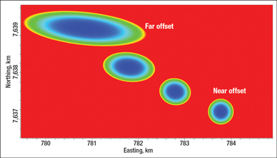
Simple inspection of the migration impulse response for a zero-offset trace shows that the sampling requirement changes with time. Furthermore, the size of the Fresnel zone also changes with offset and with the bandwidth of the seismic signal. Figure 1 shows the Fresnel zone for a single horizon at different offsets. The size differences show that use of a constant bin dimension with only a small “flex” would not be the best decision.
In the past, Fresnel zones have occasionally been used in seismic survey planning to develop required apertures or sampling relationships. Fresnel zones are often computed using a zero-offset assumption and constant velocity, but in a practical sense, this is a poor representation of the “area of influence” of the Fresnel zone. The Fresnel zone concept has been well understood, but no practical way had been identified to use this concept to guide seismic acquisition.
The concept of the Fresnel zone suggests an “area of influence” around a ray; this area of influence can be described in terms of the travel time to a point in the subsurface and the change in this travel time associated with one-fourth of the wavelength. For a given reflection event in the subsurface, seismic traces—which have reflection ray “points” within the Fresnel zone—will contribute constructively to the output seismic trace at the center of the Fresnel zone when data is migrated. And, conversely, a trace with a ray “point” at the center of the Fresnel zone has actually sampled all points on the reflection event within the Fresnel zone. Therefore, understanding the shape of Fresnel zones is required when assessing the adequacy of coverage in the 3D survey. In pre-stack migration, all of the traces within this area affect the output trace at the center.
The shape of the first Fresnel zone is not a circle, but an ellipse that can be defined by its dimensions parallel and perpendicular to the shot receiver axis. For finite offsets, both dimensions are larger than the zero-offset circle, and the ellipse is elongated along the shot receiver axis. For realistic velocity regimes (e.g., where velocity increases with depth), the ellipse gets bigger, and in some cases much bigger, than in the constant-velocity situation.
Figure 1 shows Fresnel zones computed for an event at 3,000-m depth for offsets of 150 m (bottom right), 2,550 m, 5,150 m and 7,550 m (top left). In the presence of a velocity gradient, the finite offset Fresnel zone is considerably larger than the straight ray equivalent. Note that the area of influence for the far trace in the figure spans nearly 2 km in the inline direction and over 0.5 km in the crossline direction.
 |
|
Fig. 1. Fresnel zone comparison for different offsets.
|
|
Pre-stack migration will take the data from all the traces in this area and combine these to form an output at the desired location. The criteria for sampling are now different from the common flex “binning” criteria. Conversely, the Fresnel zone defines the area of the subsurface that has been sampled by a single seismic trace. If all parts of a surface are covered by the Fresnel zones of multiple traces, then the surface has been examined everywhere. If the Fresnel zones do not overlap on the surface, then there are some parts of the reflector that have not been sampled, and they cannot be imaged correctly.
It is important that the Fresnel zone (and not the output bin) at any location has been adequately sampled. This suggests several improvements that can be implemented in the way that marine seismic is acquired. One of these would be to address coverage needs for shallow targets, or high-resolution surveys. If the Fresnel zone for a certain offset is smaller than the bin dimension (remember that the size of the Fresnel zone decreases with higher seismic frequency bandwidth), the subsurface will not be fully illuminated by that offset. Furthermore, if that small Fresnel zone does not extend to the actual bin center, it will not be possible to interpolate toward the bin center, and it is well known that imaging will suffer if pre-stack migration is performed using an irregular input grid.
If a second trace of that particular offset would be present in the bin, for instance from the acquisition of infill lines, current binning practice may select the trace nearest to the bin center. However, as this trace may have been acquired with a different azimuth and under different conditions, the imaging results for this offset often show some degradation.
It follows that the best method of ensuring good shallow imaging is to acquire data such that a nearest-offset trace falls at the center of the bin. However, as mentioned above, this does not guarantee that the illumination is complete. Shooting along pre-plot source positions is more commonly associated with requirements for 4D or wide-azimuth 3D, where the intent is to be able to repeat shot locations. In fact, it is likely to improve conventional 3D acquisition as well.
Sampling requirements for longer offsets or conventional target depths should be determined by adequate sampling of the Fresnel zone (i.e., the trace requirements for input to migration), and not by the dimensions of the bins’ output from migration. In fact, relatively large holes in long-offset coverage can be accommodated if the Fresnel zones are still well sampled. This leads to the concept of Fresnel zone binning (FZB).
FRESNEL ZONE BINNING
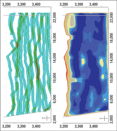
If the 3D seismic survey targets are relatively well understood before the start of a survey, it is possible to determine the shape and size of the Fresnel zone for every trace as it is acquired for particular target depths, as well as the change of the shape of the Fresnel zone with offset and the tolerance to streamer position with offset. For a single trace, rather than simply entering a “1” as the fold contribution to a single bin at the midpoint, we can enter the weight values associated with the contributions that this trace will make to the output bins from migration, since the trace energy will be spread across many bins as part of the migration step. Figure 2 shows the difference between conventional binning, based on simple trace count, and Fresnel zone binning using the true amplitude contribution of the acquired traces according to the Fresnel zone weights.
 |
|
Fig. 2. Bin coverage for a single offset, using a conventional bin approach (left) and Fresnel approach (right) for real data.
|
|
FZB software performs this analysis for all traces, concurrent with the acquisition, and the effective contribution to each bin at each offset is computed and assessed for adequacy of coverage. This can take into account specific target depths, offsets used, frequency content of the seismic signal and angle of incidence selection.
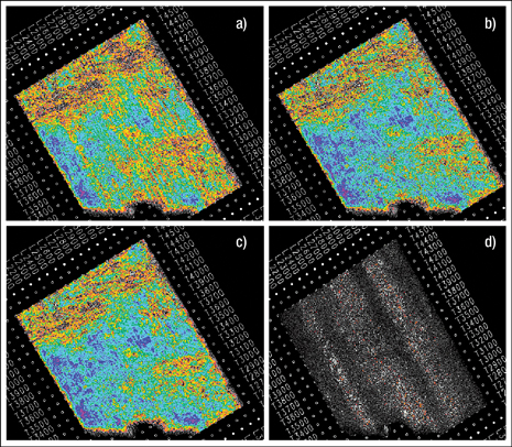
Figure 3 shows a comparison of amplitude maps along one horizon for the different processing results. Figure 3a shows the amplitudes for the conventionally processed volume of prime data only. Stripes of amplitude anomalies are clearly visible, mainly caused by low or zero folds for longer offsets (missing infill). Figure 3b shows that the problems are resolved if all infill lines are used. However, an almost identical result, shown in Fig. 3c, can be achieved by using the prime data alone and a wavefield-consistent processing route. The amplitudes in the difference plot in Fig. 3d are at their largest around 18 dB down on the horizon amplitude, and significantly smaller in most places. As it is impossible to replicate the exact noise conditions during acquisition by means of interpolation, it is not surprising that the largest differences seem to be random and concentrated around the areas where infill was acquired. Evaluation of the amplitude difference map (equivalent to evaluating FZB plots) shows that none of the acquired infill lines, based on traditional fold-based coverage analysis, were actually required. Reprocessing of the data set with various combinations of infill lines shows that the optimal result was achieved when the input data met the FZB threshold criteria and the data were processed through a wavefield-consistent processing route.
 |
|
Fig. 3. The amplitude map when a) only prime data is processed, b) all available data are processed (prime plus infill), and c) only prime data is processed but with a special processing flow involving wavefield-consistent interpolation; and d) the difference plot. A common amplitude plot scale has been used for all four figures.
|
|
In this example, the infill assessment based on the FZB criteria would have greatly reduced infill requirements (in fact, no infill would have been necessary), demonstrating the FZB method’s potential to reduce acquisition costs.
FZB IMPLEMENTATION
The FZB analysis has been implemented in a user-friendly, powerful application that allows for the selection of parameters prior to commencement of the survey, such as depths of the objective horizons, range of offsets, frequency spectra and velocity functions. Then, concurrent with its acquisition, the acquired seismic data is analyzed and aggregate Fresnel zone contributions of the traces acquired are created.
Based on set criteria for allowable attenuation from the full Fresnel zone contribution, an infill program is devised. Of course, the targeted effect of the planned infill program can be analyzed immediately by including the P1/90 data of the proposed infill into the integrated analysis.
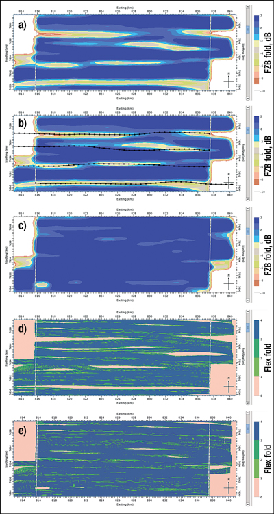
An example of infill planning with FZB is provided in Fig. 4. Figure 4a shows the FZB analysis (longest offset) for a section of the survey with only prime line acquisition. The proposed infill tracks are illustrated in Fig. 4b, and Fig. 4c shows the updated FZB plot after infill acquisition. Figures 4d and 4e show conventional flex binning coverage plots before and after infill. Note that further infill would be required to satisfy conventional binning specifications.
 |
|
Fig. 4. Fresnel zone binning compared to traditional coverage analysis. FZB analysis is shown for a) prime lines only, b) prime lines with suggested infill, and c) prime lines plus infill. Conventional binning analysis is shown for d) prime lines only and e) prime lines plus infill as suggested by FZB analysis.
|
|
ADDED VALUE OF STREAMER STEERING
Combined with the FZB analysis, steerable streamers can be positioned in a manner to optimize subsurface seismic coverage. After calculating the coverage tolerances for all offsets using the Fresnel zone analysis, the maximum lateral distance between adjacent streamers can be calculated along each streamer, and the lateral steering can assist in positioning the streamers to maximize coverage. Separation variations at longer offsets are less critical than variations at shorter offsets, and the streamers are steered to minimize the impact of position changes. This can be utilized as part of the pre-planning for a survey, but additionally the ability to steer the streamers during acquisition can further reduce infill based on Fresnel zone criteria.
Utilization of steerable birds has also proven successful for 4D purposes, and when applying new acquisition techniques. Lateral steering has been used when shooting in turns, and two surveys of fan-mode acquisition have been executed. In the latter case, the devices are used to create a larger separation in the tail of the streamers, which helps reduce the infill rate. This technique can be used in conjunction with Fresnel zone binning as previously discussed.
Other benefits of the lateral controllers include more efficient equipment deployment and recovery, and safer work boat operations because of improved streamer control. Enhanced streamer control also mitigates risks when working in obstructed areas.
INTERPOLATION
Prior to pre-stack migration, interpolation techniques are used to construct a regular grid from traces within every Fresnel zone. As the Fresnel zones may be large for deeper targets, it is essential that high-quality algorithms, including the ability to interpolate multiple and conflicting dips, are used. Newly developed software based on the frequency reconstruction technique known as matching pursuit is used to construct the regular seismic data in three or more dimensions.
The principle is similar to Fourier-based regularization methods such as anti-leakage Fourier transform (ALFT) or projections onto convex sets (POCS), in which the seismic data is iteratively projected to local Fourier function. The method assumes that in a small data window, seismic data contains mainly linear events. Therefore, each slice of temporal frequency in the frequency-wavenumber (f-k) domain is relatively sparse. In each analysis window, the probability of linear seismic events within a certain range of dip from available seismic data in that window is determined first.
A Fourier spectrum is constructed to fit with existing data and pre-calculated dip preferences. The method is capable of interpolation across large gaps in coverage and may also interpolate events with conflicting dip. The anti-aliasing procedure permits interpolation of steeply dipping seismic events such as diffraction curves.
CONCLUSION
Once the size of the Fresnel zone is understood, the requirements for coverage as a function of offset, angle of incidence, frequency content and depth can be evaluated accurately, assuming that pre-stack migration will form part of the processing sequence for data. The same criteria can be used to set steering tolerances for streamers during acquisition, to further minimize the amount of infill required in a marine streamer survey.
At longer offsets and later times, the common binning parameters may be inappropriately small. It is relatively easy to establish criteria for adequate distribution of sampling within the Fresnel zone, and this can be used to guide acquisition, particularly the requirement to acquire infill data in a marine environment. With different tolerances resulting between near and far offsets, steerable streamer technology can be used to position the streamers in a manner to optimize coverage. Finally, the use of high-quality interpolation algorithms is essential to obtain the desired results. 
|
THE AUTHORS
|
 |
Paul Young has over 20 years of experience in marine seismic acquisition and has filled management positions in both oil companies and seismic service companies. After spending seven years in field positions throughout Southeast Asia, Mr. Young spent four years in Singapore in business development roles. In 2000 he moved to Perth, Australia, where he has worked in numerous business development, operational and HSE roles. Mr. Young is Vice President in the Asia-Pacific region for Fugro-Geoteam.
|
|
 |
David Monk is the Director of Geophysics at Apache Corp., with responsibility for worldwide seismic activity. Having completed a PhD in physics, he worked on seismic crews in Nigeria for two years and has subsequently been involved in seismic processing and acquisition in most parts of the world. Dr. Monk has received “best paper” awards from the Society of Exploration Geophysicists (SEG) and the Canadian Society of Exploration Geophysicists, he was the first Vice President of SEG in 2006.
|
|


