An investigation into the flow of gas at a shallow water platform after the 95⁄8-in. casing was cemented revealed that following good cementing practices could have prevented a potentially serious well control incident.
Ray T. Oskarsen, John W. Wright and Danny Walzel, Boots & Coots
Although flow after cementing is common, usually it occurs from the surface casing at shallow depths. However, a well control incident that occurred on a shallow-water platform demonstrates that flow after cementing can take place for deeper casing strings. In this case, the 9 5⁄8-in. casing had been set and cemented following the cement program typically used in the area. The well began flowing while the crew was installing the slips, 4 hr and 45 min. after cement displacement. The shut-in casing pressure (SICP) rapidly built above the maximum allowable annular shut-in pressure, prompting an extensive mitigation operation until the well was controlled.
A post-incident investigation indicated that the influx occurred as a result of hydrostatic loss during the cement transition. The investigation concluded that very simple measures, such as following good cement practices, could have been sufficient to prevent the incident.
Gas flow after cementing, which was first recognized in the early 1960s, can be attributed to a number of factors related to cement chemistry and physical properties, mud displacement, wall cake removal, casing centralization, hole inclination, formation permeability and pore pressure.1,2 Considerable effort has been exerted to find solutions, but despite all the research and advancements, flow after cementing still is a relatively common occurrence around the world. In a study of the US Outer Continental Shelf from 1992 to 2006, it was found that cementing problems were the leading contributing factors to blowouts. Compared to previous blowout studies,3 the percentage of Gulf of Mexico blowouts occurring during or after cementing has increased.
SEQUENCE OF EVENTS
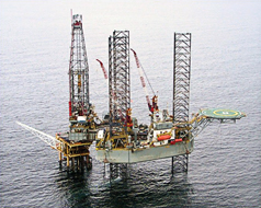
The subject well was drilled from a six-slot steel platform in 132 ft of water using a cantilever jackup, Fig. 1. After drilling the 16-in. hole to 6,570 ft MD, the rig crew was unable to run the 13 3⁄8-in. casing to bottom. The original hole was abandoned unplugged and a sidetrack was drilled. The 13 3⁄8-in. casing eventually was set at 6,356 ft, about 20 ft away from the initial 16-in. hole.
 |
|
Fig. 1. Six-slot steel platform with a cantilever jackup in 132 ft of water.
|
|
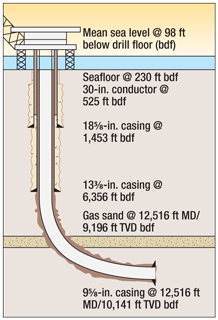
The 12¼-in. hole section was started with a 10.2-lb/gal ester-based mud (EBM) and later raised to 11.1 lb/gal before drilling through a geopressured sand at 12,516 ft MD. The inclination at the end of the hole section at 15,000 ft was fully horizontal, Fig. 2. Because this was a trial well, a vertical dryer was used to clean the cuttings before overboard discharge. It was recommended that three to four stages of centrifuging be performed after the vertical dryer to remove all fine cuttings. However, only one stage was used, which proved to be insufficient. At the end of the hole sections, the mud contained 8–11% low-gravity solids (LGS) comprising fine clays.
 |
|
Fig. 2. Inclination at the end of the 12¼-in. hole section at 15,000 ft was fully horizontal.
|
|
Adding to the mud problems, it was believed that the dispersed clays and barite sag caused density and viscosity stratification up and down the well when circulation was stopped. When the 9 5⁄8-in. casing depth was reached, the trip out of the hole was complicated by numerous overpulls requiring back-reaming most of the way. It took 63 hr to pull out of the hole; another 23 hr passed before casing operations commenced. Consequently, the bottom of the well was without circulation for 3½ days. Before the 9 5⁄8-in. casing was run, the drilling fluid reportedly was so viscous it would barely pour from a cup.
Due to problems getting the 13 3⁄8-in. casing to bottom earlier, centralizers were placed only on every other joint above the shoe track. There were no additional problems in running the casing. When the 9 5⁄8-in. casing was on bottom, about 1.5 annular volumes were circulated and the gas readings were reduced to background levels.
The cement program used for the 9 5⁄8-in. casing was similar to that of other wells in the area. To preserve the EBM for use in another well, it was displaced with a sacrificial water-based mud (WBM) spacer ahead of the cement slurry and followed with a 44-bbl preflush spacer. The extended 12.5-lb/gal lead cement covered the hydrocarbon-bearing sand. Top of cement was not taken into the 13 3⁄8-in. casing. The 15.8-lb/gal tail cement was planned to cover the bottom 948 ft of the casing. The cement was displaced with 11.1-lb/gal EBM.
The cement train was pumped as designed without incident. About 295 bbl of properly treated WBM was dumped overboard during the last phase of the cement displacement. Following the cement program, the plug was bumped at the calculated stroke count and a text-book cement job was reported in the daily drilling report.
However, while installing the seal assembly, the rig crew noticed that the annulus began flowing. At this point, a total of 4 hr and 45 min. had passed since the plug was bumped. The initial SICP of 1,400 psi increased to 1,850 psi, where it remained steady. This was sufficient to cause fracturing of the 13 3⁄8-in. shoe (assuming 11.5-lb/gal mud to the shoe). The annular pressure was reduced to about 145 psi after 12.3-lb/gal WBM was lubricated in the annulus over 21 cycles.
After the surface pressure was brought under control, diagnostic logs consisting of noise, temperature, segmented bond log (SBL) and compensated neutron log (CNL) were run to evaluate potential cross-flow and cement integrity. There was not a substantial cross-flow taking place behind the casing string, according to the temperature and noise logs. The CNL indicated that there were areas of trapped gas behind the casing, while the SBL indicated a very poor bond along most of the logged borehole. The bond was particularly unacceptable across from permeable sands and along the low side of the borehole. The bond quality followed the gamma ray nearly exactly as it moved between the sand and shale sequences. However, there appeared to be a section of about three joints that had reasonable bond just above the gas-bearing sand, which ultimately may have prevented a cross-flow scenario.
Similar cement programs for the 9 5⁄8-in. casing had previously been employed successfully in other wells in the area. However, this well differed considerably from its offsets, including the presence of a geopressured gas zone above the 9 5⁄8-in. casing shoe, poor casing centralization and highly viscous EBM that contributed to barite sag. Poor mud displacement could have been another contributing cause of the well control incident, resulting from insufficient casing centralization and the viscous mud. However, it appears that the primary cause was inadequate lead slurry design for this particular situation. The tail slurry, which had right-hand-set properties, did not cover the hydrocarbon zone. The lead cement covered an excessively long section where fluid loss and hydrostatic loss could occur.
Many well control incidents have been reported as a result of gas flow after cementing. In this case, it appears that the cement set after the influx started and limited the volume instead of turning into a surface, broached or underground blowout. One of many fears was that a sustained gas flow could use the abandoned 16-in. hole as a conduit to broach below the platform.
INVESTIGATION
After the well was brought under control, considerable effort was given to determining the technical causes of the incident and how similar situations could be prevented in future cement jobs. There are many opportunities for gas migration to occur from the time a string of casing has been set until the cement is an impermeable solid. The post-incident analysis revealed some of the potential causes of the gas flow, including centralization, mud conditioning, displacements, cement spacer, fluid loss, free water and cement gelation.
Centralizers were placed only on every other joint above the shoe. The casing, therefore, would be eccentric in the borehole lying on the low side. This situation would leave immobile viscous mud on the low side of the hole in the high-angle sections, which would be extremely difficult to remove by circulation alone. Additionally, cement could not be placed completely around casing in places where the casing was laying against a formation.
The EBM system was reported to be in poor shape, primarily due to a high percentage of LGS (8%–11%) at the end of the hole section. There were indications of barite sag when the mud was left static in the hole. Samples of the mud were taken showing separation with a layer of ester on top after only 12 hr. The hole trajectory had a high inclination going to horizontal over the hydrocarbon zones of interest. It took 3½ days to back-ream out of the well. Nearly five days passed between the time the 12 1⁄4-in. hole reached TD until the 9 5⁄8-in. casing was on bottom. At this point, the mud was reported to be extremely viscous (210-cP plastic viscosity and 11.6 lb/gal) at spots during circulation while running the casing. This long static period potentially would create barite sag on the low side of the hole while static filtration would deposit a thick filter cake on the walls of the borehole across the permeable sands.
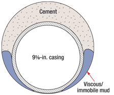
The EBM was displaced using 547 bbl of a sacrificial WBM system, which, according to the contractor’s inventory sheets, basically comprised water, barite and 50 kg of polymer viscosifier. This displacement fluid was not engineered, but rather mixed on site. The viscosity, yield point, gels and water-loss properties were not measured. While no records of its rheological properties were recorded, the density was documented as 11.5 lb/gal. The WBM was seen at the surface earlier than expected by about 50 and 145 bbl, depending on hole size used, gauge or 10% excess. Since the first 44 bbl of returns were contaminated with EBM, this suggested that the viscous and immobile EBM on the low side of the hole was bypassed and the filter cake was left across the permeable sands, Fig. 3. The contaminated mud returns also indicated that the interface between the two fluids was not flat. No reciprocation of the casing was attempted during circulation.
 |
|
Fig. 3. High-viscosity ester-based drilling fluid bypassed by displacement mud, spacer and cement.
|
|
Most of the circulation rate during displacement was kept constant at 13 bbl/min. The volume of the preflush spacer between the WBM and the lead cement was 44 bbl, which yields a wellbore contact time of 5 min. The rule of thumb for good hole cleaning is a minimum contact time of 8–10 min. and displacement in turbulent flow-regime when possible. It is unlikely that the mud push spacer cleaned the immobile mud and filter cake as this would likely have caused continuous mud channels in the annulus.
The 11.9-lb/gal preflush had a reported viscosity of 22 cP, which was lower than the EBM. Also, there did not appear to be any surfactant to water-wet the casing/formation. The lack of a surfactant will leave an oil layer on the pipe and formation, preventing bonding of the cement. The result could be a micro-annulus, which in this case likely contributed to the poor cement job and the well control incident.
Some degree of fluid loss from the cement slurry to surrounding formations will always occur when the hydrostatic pressure exceeds the formation pore pressure. During the cement hydration process, the volume shrinks. Consequently, the hydrostatic pressure that the fluid column exerts will decrease. When fluid loss occurs above a gas-bearing zone, it amplifies the loss of hydrostatic pressure, which increases the potential for gas influx. The industry rule of thumb is that API water loss in cement slurries should be less than 50 ml/30 min. to minimize this effect. The API fluid loss reported for the lead slurry was 135 ml/30 min.
The 12¼-in. hole section was kicked off from vertical to a final wellbore inclination of 90°. If the cement slurry allowed for free water release, the water would coalesce to form channels for gas migration on the high side of the borehole. Zero free water is recommended for cements with open hydrocarbon zones to be isolated.4 The lead slurry for this cement job had free water of 0.6 ml/250 ml.
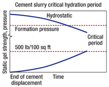
As mentioned, many potential causes existed for the poor cement job, but none of them would have caused the well to fall underbalanced. Consequently, another factor likely occurred that reduced the pressure in the wellbore to the point where a gas influx could occur. The static gel strength in a cement will begin developing when the displacement ends and the well is static. Once the static gel strength has reached about 500 lb/100 sq ft, gas will no longer be able to percolate through the cement. During this process, the water volume is reduced by hydration and filtration, which also reduces the pressure in the cement. Experiments have shown that the hydrostatic pressure will decrease during this period to the level of the mix water. Hence, a well can become underbalanced if a long column of cement is covering a gas-bearing sand, as was the case for this well.
A critical period occurs once the hydrostatic pressure of the cement column falls below the pore pressure until the static gel strength reaches approximately 500 lb/100 sq ft, Fig. 4. Many cement slurries are designed specifically to reduce the critical transition period. One such slurry is the right-hand-set cement, which remains fluid and experiences little gel-strength increase while the volume is reduced. This continues for a relatively long time until the cement begins to develop strength. At this point, the gel strength will increase very rapidly, resulting in a short critical period.
 |
|
Fig. 4. The critical period after cement displacement when gas may migrate.
|
|
In this cement program, the tail cement had right-hand-set properties as opposed to the lead slurry. If the tail cement would have covered the gas-bearing sand, it might have prevented the well control incident.
CEMENTING RECOMMENDATIONS
Since no two wells are exactly the same, using one generic procedure is insufficient for all operations. Some of the well conditions that are constantly changing include hole cleaning, hydraulics, fracture gradients, percentage of openhole annular volume relative to displacement volume, presence or absence of pay, and hole clearance. The most important aspects of casing, liner and cementing operations are the identification of objectives and risks for a particular job and the selection of equipment and procedures to mitigate the risks while achieving the job goals. As such, every cement job should be designed to address the risks and objectives specific to the well.
The following good cement practices could aid in preventing flow-after-cementing from occurring:
Conduct a risk analysis to mitigate potential well flow after cementing operations on all casing and liner jobs where hydrocarbon zones are open and need isolation.
Keep the well closed while waiting on cement until after the cement transition time has expired. Some operators prescribe holding slight backpressure on the annulus while waiting on cement, to evaluate any losses and attempt to maintain overpressure on the reservoir during transition.
Develop a good pit management plan when multiple fluids require displacement to avoid dumping spacers overboard. This will ensure that gain/loss information is available during displacement for well control purposes.
The mud used to drill the hole section should be conditioned and treated to limit viscosity to what is required for the hole conditions and to have water loss to control a thin filter cake across permeable sands.
Engineer all displacement fluids (compatibility, volume, rheology, density and chemistry) and the pump rate (laminar or turbulent) based on rig equipment, mud to be displaced and hole conditions. For laminar flow, spacer density and viscosity should be higher than the fluid it is displacing. Fluid pumped should have 20% more frictional losses than fluid displaced.
Be sure to adequately centralize the casing in high-angle wells that require hydrocarbon zone isolation, and to maintain zero free water in cement slurry chemistry. The latter is particularly important in deviated wells.
Limit the height of low-density extended lead cement without right-hand-set properties when hydrocarbon zones need to be isolated, to avoid long columns where hydrostatic loss may occur and induce an influx during cement transition. Consider stage cementing if necessary.
Right-hand-set cement (or another comparable gas migration cementing technique) should be used above all hydrocarbon zones. As a rule of thumb, API fluid loss should be less than 50 ml/30 min.
If gas zones are present and a non-gas blockage slurry is used, consider treating the cement with surfactants.
In all cases, attempt to engineer the cement job so that it sets from the bottom up.
Finally, batch mixing should always be considered if it is practical. 
LITERATURE CITED
1 Watson, D., Brittenham, T. and P. L. Moore, Advanced Well Control, SPE Textbook Series, Vol. 10, Richardson, Texas, 2003, pp. 237–241.
2 Cheung, P. R. and R. Beirute, “Gas flow in cements,” SPE 11207 presented at the SPE Annual Technical Conference and Exhibition, New Orleans, Louisiana, Sept. 26–29, 1982.
3 Izon, D., Danenberger, E. P. and M. Mayes, “Absence of fatalities in blowouts encouraging in MMS study of OCS incidents 1992–2006,” Drilling Contractor, July–August 2007, p. 84.
4 Webster, W. W., “Flow after cementing: A field and laboratory study,” SPE 8259 presented at the SPE Annual Technical Conference and Exhibition, Las Vegas, Nevada, Sept. 23–26, 2007.
|
THE AUTHORS
|
 |
Ray T. Oskarsen is the Technical Services Manager for Boots & Coots, where his duties include the development of well control-related risk management technologies, software and processes. Dr. Oskarsen holds a bachelor’s degree with honors in mechanical engineering from the University of Surrey and a master’s degree and PhD in petroleum engineering from Texas A&M University.
|
|
| |
John Wright formed John Wright Company in 1989 to provide blowout control engineering services for managing relief wells and underground blowouts. Since then, he has designed and supervised 40 relief well and borehole intersection projects around the world. He is currently Senior Vice President of Technology for Boots & Coots following its acquisition of John Wright Company in 2009. Mr. Wright has authored 18 relief well and blowout-related industry publications. He earned a BS degree in mechanical engineering from Texas A&M University.
|
|
| |
Danny Walzel is a Well Control Engineer for Boots & Coots, where he has worked on numerous well control situations around the world, including subsurface and surface blowouts. Mr. Walzel received his BS degree in petroleum engineering from Texas A&M University and is a licensed professional engineer in the state of Texas.
|
|


