The treatment process investigated includes electro-coagulation and advanced mechanical separation, as well as a low-pressure, chemical affinity-based filter.
Curt Johnson, Custom Water Solutions; Judd E. Sundine, Sundine Enterprises; and Mike Curtis, RMOTC
Large volumes of contaminated water are typically produced during the course of oil and gas operations, from drilling, completion and production activities. Disposal or treatment of this water poses significant operational and economic challenges to oil and gas producers. In June 2009, Custom Water Solutions partnered with the Rocky Mountain Oilfield Testing Center to test a multistage fluid filtering system using new mechanical separation technology for cleanup of produced water and of mud pits.
TEST SEQUENCE
RMOTC partnered with Custom Water Solutions to test oilfield wastewater from RMOTC’s test site at the Teapot Dome oil field north of Casper, Wyoming. The test was performed June 15–17, 2009, at the laboratory and workshop of Custom Water Solutions in Mills, Wyoming. Testing, sampling and sample handling were witnessed by a RMOTC staff member.
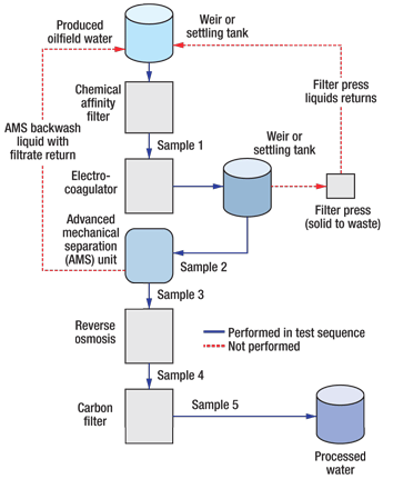
The water treatment system tested consisted of three principle stages: 1) an oil separation stage using both gravity separation and a filter medium with chemical affinity to hydrocarbon compounds; 2) a pre-treatment stage in which suspended particulate matter was removed; 3) a reverse osmosis (RO) and carbon filter stage to remove dissolved salts and minerals. Figure 1 illustrates the processing sequence.
 |
|
Fig. 1. Water treatment test procedure flowchart.
|
|
On June 15, 250 gal of produced water were collected from RMOTC’s field test site, also known as Naval Petroleum Reserve No. 3 (NPR-3). The fluids were taken from the T/B-1-20 battery, which is a collection point for produced liquids from the Second Wall Creek Formation. The water was pumped into a polypropylene transport tank in the late morning when the battery tank was almost full. Based on the large volume of the storage battery tank (about 400 bbl), it was considered reasonable to assume that, before the test water was taken, most solids had time to settle to the bottom of the tank and the free oil had completely separated from the water in the tank. Because processing did not take place until the following day, the produced water contaminants had the opportunity to continue to settle and separate overnight. However, no oil film was observed the following day.
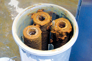
Chemical affinity filtering. On June 16, the water was circulated through a 10-in. filter unit containing three new filter cartridges designed by MyCelx Oil Removal Technologies. The filter media employs a patented surfactant filter material that exhibits high chemical affinity to hydrocarbon molecules, and uses that affinity to remove residual oil from the produced water. The media also filter out chlorinated solvents, PCBs, organic solvents, pesticides, biocides and organically bound metals. Figure 2 shows used filter cartridges (from a different test) showing particulate matter that has built up on the outside of the filter cartridges.
 |
|
Fig. 2. Used chemical affinity-based filter media.
|
|
The chemical affinity-based filtering process consumes very little energy, requires very little differential pressure (less than 1 psi), and is scalable; multiple cartridges can be installed in parallel to increase process flowrate. Individual cartridges are available for flows ranging from 1 gal/min. to 780 gal/min.
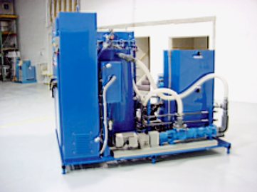
Electro-coagulation. Next, the water was treated with an electro-coagulator, Fig. 3. The test employed a used laboratory unit that ran on a 220-V supply with 180 A (39,600 watts). Coagulation has the effect of ionizing small solid particles suspended in the treatment water as the water passes between a series of plates having opposing electrical charges. Solid suspended particles become electrically charged and, therefore, electromagnetically attracted to each other. The particles coagulate into coarser particles that either settle as a result of their increased mass or can be more readily filtered due to their increased size. The resulting solids are in an oxide form that can be put into a non-hazardous landfill after separation.
 |
|
Fig. 3. Electro-coagulation unit.
|
|
The electro-coagulation process releases hydrogen, which tends to foam and pick up particulate matter. This foam was skimmed from the system. Electrocoagulation makes constituents in the produced water separable, while advanced mechanical separation (AMS) filtering is used to actually remove them from the water.
Electro-coagulation is a scalable process and generally can process flowrates in multiples of 500 gal/min. However, the unit used in this test was capable of conditioning 1 gal/min.
Settling. The electro-coagulated water was allowed to stand overnight in a holding tank. Although overnight holding was not an intended (or a necessary) part of the test sequence, it was advantageous because it allowed the coalesced suspended particles to settle overnight, thereby reducing the load on the AMS media filtering step.
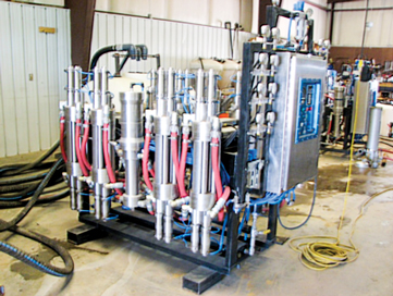
AMS filtering. On June 17, 60 gal of water was processed through the AMS unit, which consisted of eight filter units each with eight cartridges, Fig. 4. Under high pressure, the water passes through the media filters, which trap suspended particles greater than 5 microns. Pressure gauges on the control panel indicate the pressure differential across the media cartridges. Periodically, as the unit detects a pressure gradient across the filter, the unit enters a backwash cycle to clean the filters. Filtrate is collected, then returned to the weir tank or disposed of.
 |
|
Fig. 4. The advanced mechanical separation unit used in the test lab, showing four of eight filter cylinders and one of two hydraulic backwash pumps.
|
|
During the test process, hydraulic backwash of the filter cartridges occurred about every two minutes using 5% of the total fluid volume. In a production scenario, that backwashed liquid would be returned to the start tank, and the solids would be compressed through a filter press.
AMS is a scalable process. The single unit used in this test was capable of filtering 8 gal/min. to 75 gal/min. Units capable of flowrates greater than 100 gal/min. are available.
Reverse osmosis. Forty-five gallons of partially processed water was passed through an RO filter. The filtering process was accelerated by two 150-psi pumps plumbed in an inline configuration. The RO unit used in the test contains a very fine, strong, semi-permeable membrane that removes, under pressure, dissolved salts including fluoride, chlorine, calcium and magnesium.
RO filters also remove some bacteria and viruses. Periodically, the solute that concentrates on one side of the membrane must be flushed to remove the trapped oxides. Membrane pore sizes can vary between 0.1 nm and 5,000 nm. Systems are available in 500-gal/min. increments. RO is a high-pressure and relatively slow, but scalable, process.
Carbon filtering. As a final step in the process, a few gallons of processed water were then passed through a non-industrial carbon filter. Industrial units are readily available.
Commonly called a polishing filter, the carbon filter is a block of activated carbon that removes any negatively charged contaminants from the processed water by means of chemical absorption. The carbon used has a very large surface area (1 lb has 100 acres of surface area), and it is activated with a positive charge to attract the contaminants. Carbon filtering removes chlorine and volatile organic compounds. The efficacy of carbon filtering is related to length of exposure and flowrate. Carbon filters can also trap particles of sizes ranging down to 0.5–50 microns, depending on filter specifications. Carbon filtering is a scalable process.
Softening (commonly applied to reduce scale), pH adjustment and ultraviolet filtration (to neutralize bacteria) were considered but not included in the test sequence.
RESULTS
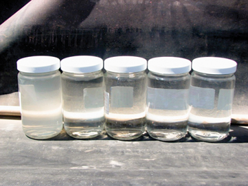
Fluid samples for lab analysis were taken at the following stages of the test: start water (collected from the water zone in the T/B-1-20 battery tank), post-chemical affinity filtration, post-electro-coagulation (EC), post-AMS, AMS reject (not lab tested), post-RO and post-carbon filter (CF). Figure 5 shows the comparative clarity of each of the water samples analyzed.
 |
|
Fig. 5. Water samples taken (from left to right) before treatment, after electro-coagulation, after AMS, after RO and after carbon filtration.
|
|
Five samples were taken at each stage of the test and then sent for analysis to Energy Laboratories in Mills, Wyoming.
Notable changes in ions, metal content and other properties resulting from the water processing sequence are summarized in Table 1. It can be observed that electro-coagulation is effective at reducing calcium, magnesium and sulfate. AMS is most beneficial at reducing turbidity and metals, and RO is effective at further reducing turbidity and mineral ions from the produced oilfield water.
| TABLE 1. Produced water treatment results by stage |
 |
During the test, the following were removed from the water:
• 93% of CO3, CaCo3, HCO3, calcium, chloride, magnesium, potassium, sodium and iron
• 100% of CO3, calcium, magnesium, potassium and iron
• 94% of total dissolved solids (TDS)
• 99% of turbidity.
The results reflect the equipment used and the processes and procedures applied. The process is customizable (with cost benefit impact) to meet the intended use of the processed water and the volumes required. It was determined that the treatment sequence employed could be improved by customizing the process, such as by maintaining a longer residence time in settling tanks. Further improvements could be realized by balancing the pH (which could further improve coagulation and flocculation), by using finer filter media elements for the chemical-affinity, AMS, RO and carbon filter elements, and by reducing the flowrate. 
|
THE AUTHORS
|
|
Curt Johnson is the President of Custom Water Solutions, and maintains businesses in Pagosa Springs, Colorado, and Casper, Wyoming. His primary business is home construction, but he has spent the past 2½ years gaining knowledge regarding water treatment in the oil industry in Wyoming. Mr. Johnson’s company has run several hundred water tests on many types of wastewater.
|
|
|
Judd E. Sundine has more than 36 years of experience in the horticulture, wastewater and environmental fields. He earned a degree in horticulture from Colorado State University and is President and Chief Technical Officer of Sundine Enterprises Inc. Mr. Sundine is a specialist in water and wastewater remediation, bioremediation, erosion control, soil amendments, pond aeration, algae and weed control, oilfield produced water reuse and reclamation, and animal waste remediation.
|
|
|
Mike Curtis has more than 30 years of oilfield experience with expertise in international field development, production optimization and technology development. He joined the Rocky Mountain Oilfield Testing Center project management team in 2008 and has special interest in unconventional energy sources. He holds a BS degree in geology from the University College of Swansea in Wales.
|
|


