The implementation of a seabed isolation device enabled a doubling of the operating water depth capacity for operations offshore Brazil.
Brian A. Tarr, Tor Taklo, Andrew Hudson and Lisa Stockwell, Shell; and Jim Schroeder, Transocean
Surface blowout prevention (SBOP) technology extends the use of smaller, cheaper second- and third-generation rigs into water depths that cannot be achieved conventionally. Following successful drilling campaigns in Asia, Shell extended its SBOP technology to the more demanding conditions offshore Brazil with the implementation of a seabed isolation device (SID).
This article describes the first six months, starting in March 2008, of Shell’s operations with its SBOP system in the first phase of its Parque das Conchas project. The project encompasses several reservoirs in up to 6,500 ft of water located in Block BC-10 of the Campos Basin, approximately 75 mi southeast of Vitória, Brazil. Each phase of the downhole completion (production hole drillout, wellbore mechanical cleanup, displacement to brine, sand control placement and upper completion installation) has now been completed on the first batch of production wells using the SBOP system, enhanced to permit the deployment and testing of the tubing hanger and its running tool. Three production wells were completed as horizontal, gravel-packed, subsea oil production wells; this was the first time an SBOP system was deployed from a floating drilling vessel for development drilling and completion.
The seabed isolation device provides the means to isolate the well at the seabed in case the riser system has to be disconnected because of loss of vessel position (due to mooring line failure) or excessive rig motion. In mild metocean conditions, many wells have been drilled from moored rigs without using an SID. However, the SID becomes an essential component of the surface BOP system when deployed from dynamically positioned rigs or when deployed from moored rigs in more severe metocean conditions. The 13⅝-in., two-ram SID device used at Parque das Conchas was equipped with a boosted shearing blind ram (for the well isolation function) and a 7⅝-in. pipe ram (to assist with tubing hanger pressure testing). The SID was controlled from surface via a through-water broadband acoustic link or a control line umbilical strapped to the riser; this provided the required control system redundancy. Accumulators on the SID provided sufficient fluid to operate the full SID well isolation and riser disconnect sequence without re-supply from the surface. However, a fluid supply line in the umbilical was used to maintain the SID accumulators in their fully charged condition. Similarly, SID electrical power was supplied from surface via the umbilical to maintain the SID batteries in their fully charged condition.
By utilizing the SBOP system and a pre-laid mooring system, the operating water depth capacity of the moored rig used at Parque das Conchas, Transocean’s Arctic I semisubmersible, was increased from a previous nominal 3,100 ft to over 6,200 ft for development drilling and completion operations.
FIELD LAYOUT
Shell operates the BC-10 license block with joint venture partners Petrobras and India’s Oil and Natural Gas Corp. (ONGC). A total of 13 exploration and appraisal wells had already been drilled in the block with five separate, normally-pressured hydrocarbon accumulations found at relatively shallow depths, Table 1.
| TABLE 1. Five accumulations found at relatively shallow depths |
 |
Block BC-10 has the following general characteristics:
• Remote deepwater setting with shallow reservoirs
• A number of hydrocarbon accumulations dispersed over a large aerial extent throughout the block, necessitating a cluster development
• Moderate to poor crude properties (low API, high viscosity).
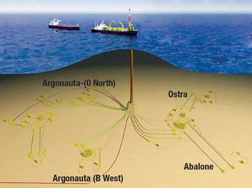
The BC-10 joint venture partners agreed to proceed with a staged development of four of the five discovered reservoirs, Fig. 1. Phase 1 of the development will consist of a centrally located FPSO connected via subsea manifolds, flowlines and risers to 10 wells—six producers and a gas disposal well in Ostra (C) Field, two wells in Argonauta (B West) Field, and a single producer in Abalone (A West) Field. Phased development of the Argonauta (O North) Field will follow, with water injection and production wells. All wells will be equipped with sand control. Phase 2 will have nominally six producers and six water injectors, with further development later. The seabed layout facilitates the use of a moored rig and permits batch drilling and completion as well as temporary suspension of wells.
 |
|
Fig. 1. Parque das Conchas Field layout, Block BC-10.
|
|
OPERATIONAL PLANS
Batching within each drillsite to maximize learning and minimize time spent preparing the rig for the next phase of operation was built into the drilling and completion sequence for Phase 1. To reduce the time required to move from well to well, the conductors were pre-installed using a subsea hammer at each drill center. A spacer spool the same height as the planned tubing head spool was added to the SBOP system. This eliminated the time and risks associated with adjusting the length of the SBOP riser system. During drilling operations on the Ostra wells, the spacer spool was latched onto the wellhead. During Ostra well completion operations, the tubing hanger spool was installed and occupied the place of the spacer spool. Both the spacer spool and the tubing hanger spool were designed to be installed using a heave-compensated landing system and to be latched and unlatched using an ROV. This setup allowed the flexibility of using a properly equipped vessel instead of relying entirely on the rig to perform the operations.
SYSTEM COMPONENTS
The SBOP system interfaces with the rig by means of a compact ball joint attached to the diverter on top of a low-pressure, triple-barrel telescopic joint. The joint connects to the top of the 13⅝-in. surface BOP stack with a 16-in. nominal ID overshot packer that fits over a corresponding mandrel on the surface BOP.
The 13⅝-in. surface BOP stack is equipped with a 5-m annular BOP, a 10-m single-boosted shearing blind ram and a 10-m double ram fitted with a 5–6⅝-in. flex ram at the top and 4½–7-in. variable bore receptacle at the bottom. A 13⅝-in., 10-m hydraulic connector connects the surface BOP to the riser.
The riser upper transition joint includes a tension ring insert that interfaces with the rig’s riser tension ring. Equipped with connectors, the 16-in.-OD riser (¾-in. wall, API grade X-80) includes bare 50-ft joints, a full range of pup joints (for accurate space-out within ±1 ft), joints with 24-in.-OD strakes and joints with 32-in.-OD buoyancy modules. The lower transition joint provides the connection to the top of the SID. The SID control umbilical and a 1-in. test/flush line are both strapped to the riser as it is run. The umbilical provides communications and power (electrical and hydraulic) for the SID-mounted control system, and the test/flush line provides means to pressure test the tubing hanger during completion operations.
The 13⅝-in., 10-m SID includes (from top to bottom) an inverted connector fitted with a re-entry funnel, a boosted shearing blind ram, a spacer spool, a 7⅝-in. pipe ram fitted with dual failsafe valves, a double-studded adapter and an 18¾-in. wellhead connector.
For drilling operations, a spacer spool with an ROV-operated wellhead connector is run below the SID. The SID is disconnected from the spacer spool when ready to start completion operations, following installation of a slim-bore tubing head spool using a heave-compensated wire system. A slim-bore 18¾-in. x 13⅝-in. wellhead system (with 9⅝-in. casing hanger profile), compatible with the 13⅝-in. nominal bore of the SBOP system, was used for all the development wells drilled with the SBOP system.
Site-specific mooring system. The Arctic I station-keeping hardware includes four double wildcats with eight anchor chains of 5,100-ft x 3-in. K4-grade cable and eight drag embedment anchors. The rig also needed a pre-installed mooring system, a concept Shell developed and implemented in the 1990s. For each of Parque das Conchas’ five drill centers, the pre-installed mooring lines were preset in the field before the rig was moved to the site. Once towed to the drill center, the rig was connected to the preset mooring lines. In both cases to date, the rig started normal operations within one day of arrival. The pre-installed mooring system had no difficulty maintaining the rig within 1–2% of water depth in normal operating sea states, with no mooring line breaks as of October 2008.
SBOP stack handling. The new hoisting system installed to move the SBOP to and from well center through the tensioner wires worked as planned. The fire-resistant SBOP hydraulic hoses were split into two bundles between the operating unit and the SBOP, and were of sufficient length to remain connected while moving the SBOP to the operating position on the top of the riser upper stress joint (USJ). The 13⅝-in. hydraulic connector at the bottom of the SBOP worked as a means to connect the SBOP to the M-70 mandrel on the top of the USJ. Only the installation of the choke and kill line gooseneck stabs required man-riding intervention to lock them in place.
SID umbilical and hose reel placement. Two SID-related reels were permanently mounted, one above the other, on the aft deck starboard adjacent to the moonpool with good line-of-sight access to well center. A common operating station located at the aft starboard corner of the moonpool provided good visibility for both activities at moonpool well center and the two stacked reels. Movable sheaves provided support for the umbilical and hose as they traveled to well center for running operations.
Installation and workover control systems (IWOCS). The IWOCS reel was lifted to its long-term location on the elevated platform on the port side of the aft deck in a single lift. The hydraulic power unit (HPU) was lifted into its location next to the crane base. The HPU for the IWOCS reel was placed on the deck below the reel to facilitate communication between the HPU operator and reel operator during operations. Both the IWOCS and HPU were installed off critical path and tested prior to the start of completion operations.
Slim-bore wellhead system. Since the slim-bore system for landing the production casing hanger used a standard 18¾-in. wellhead H-4 connector, landing the high-pressure and low-pressure wellhead housings was a standard open-water operation.
High-pressure riser system. The 50-ft, 16-in.-OD riser joints were equipped with a newly qualified 14½-in.-ID connection. Each box and pin was fitted with closed-end protectors.
RUNNING/PULLING PERFORMANCE
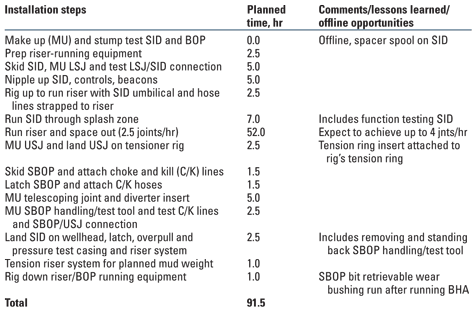
Several hands-on training sessions were conducted with different rig floor crews. However, since the planned set of 16-in. running tools was not available in time, the training was conducted on smaller tools of a different design. Thus, the tools were unfamiliar to the crew, which led to a slow first run of the riser that averaged 2 joints/hr. The detailed time breakdown data recorded during the first riser run was used to identify best times for each step and how these best times were achieved. On the second riser run, a slight improvement to an average of 2.5 joints/hr was achieved. Table 2 provides a simple expected time breakdown for running the SBOP system.
| TABLE 2. SBOP riser system running time breakdown |
 |
The riser wear management process proved effective. This process included:
• Setting maximum riser angles, measured at the SBOP and two joints of riser above the lower stress joint (LSJ) for drilling operations
• Use of casing-friendly hard banding on all drill pipe tool joints
• No pumping through BHAs that included mud motors when the bit was above the wellhead
• Use of multicycle-type circulating subs above BHAs to permit displacement of the riser; and installing a bit-retrievable 11¾-in.-ID wear bushing at the top of the SBOP.
The 1-in. pressure test hose line was run when the riser was deployed at the Ostra drill center. The test hose line was strapped to the riser; its purpose was to permit pressure testing after installation of the upper completions.
The lower shear ram in the SID was replaced with a fixed 7⅝-in. pipe ram to seal on the slick joint. During the upper completion phase of the three Ostra wells, the 7⅝-in. pipe ram performed as expected during pressure testing.
Power and hydraulic lines were added in the SID umbilical to reduce needed ROV support. There were no problems handling or strapping the heavier SID umbilical used.
The vertical tree system was an evolution of a proven Shell deepwater system. The new system included a concentric tubing hanger and smaller-diameter hydraulic tubing hanger running tool. The tubing-head spools and the trees were successfully installed and tested with a heave-compensated landing system (HCLS) using a service vessel equipped with a stern lifting/deployment frame and an ROV.
Using the spacer spool of the same height as the tubing-head spool (run below the SID) proved effective in eliminating any well-to-well adjustment of the riser system spaceout. The only operational issue that had to be resolved was that the ROV stab configuration for the spacer spool was different from that of the SID. The difference was not noted until the equipment was on the rig.
DRILLING PERFORMANCE
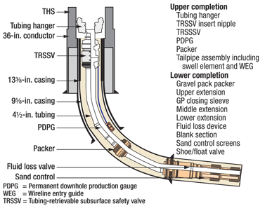
A reduced-casing scheme design was used. The basic slim-bore well casing scheme (Fig. 2) consists of a 36-in. conductor, 13⅜-in. surface casing and 9⅝-in. production casing, with an 11¾-in. liner as a contingency. This allowed setting of the 9⅝-in. production casing into the reservoir, and drilling and under-reaming of the 9½-in. open hole below the 9⅝-in. casing for gravel packing in the horizontal reservoir section.
In the Ostra wells drilled, the 9⅝-in. casing strings were run with a retractable shoe joint designed to eliminate the 12¼-in. rat hole below the casing. The retractable shoe joints were a success.
 |
|
Fig. 2. Parque das Conchas typical well casing and production interval schematic.
|
|
RISER DISCONNECT/RECONNECT
A planned riser disconnect was performed during drilling operations on the first Ostra well. The disconnect procedure in place at Parque das Conchas is summarized in Table 3.
| TABLE 3. Arctic I-specific SBOP operating procedure |
 |
Riser disconnect. The disconnect sequence went smoothly with the exception of the 1-in. test line hot stab tether parting, which led to damage of the hose connection and the ROV stab. The liftoff was smooth and controlled. The planned riser disconnect sequence was subsequently revised to include using an ROV to disconnect and secure all three ROV stabs before the actual disconnect: the 1-in. test line stab, the umbilical electrical stab and the umbilical hydraulic line stab. The disconnect could then be activated via the SID acoustic control path. A heave prediction tool was developed to improve onsite rig heave forecasting.
Riser reconnect. The first riser reconnect attempt led to damage to the connector gasket. The riser tended to bow out with only small setdown weight because the riser itself did not have a large clump weight on the bottom to pull it straight and prevent bowing and/or buckling.
The second attempt to connect with minimal to neutral weight was very difficult due to heave, but a reconnect was finally achieved.
COMPLETION PERFORMANCE
Completion operations started in August 2008 with the cleanout and gravel pack of the first Ostra well. All three upper completions were successfully installed.
Lower completion. As this was the first campaign to complete wells through an SBOP-deployed slim-bore riser in ultra-deepwater operations, the cleanout tools were specifically designed to pass through a restricted SBOP and allow effective mechanical and hydraulic cleaning action of the casing, riser and SID/SBOP. Wellbore cleanout operations were designed to reduce tripping times with the use of a slim-bore boot basket above the brush/jetting tool that could be spaced out inside the 9⅝-in. production casing while maintaining the ability to drift a dummy screen cleanout assembly through more than 3,000 ft of near-horizontal open hole for drill-in fluid displacement. This aspect saved at least eight hours of tripping time.
The lower completion hardware was deployed through the SBOP riser system. Screens were run into the open hole, and the section was gravel packed using 16/30 mesh-size sand. The mechanical fluid-loss device, a bi-directional ball valve, was closed by a shifter on the wash pipe, thus providing the primary well control barrier for moving off the well when batching. A temporary bridge plug was set in the 9⅝-in. casing as the secondary barrier. The rig then moved to batch the remaining wells by drilling the open hole and installing the sand control equipment.
Upper completion. To permit smooth passage of the tubing hanger through the change in diameter from the 17½-in. bore of the telescoping joint into the 13⅝-in. bore of the SBOP, an insert sleeve was installed to provide a temporary 13⅝-in. bore inside the top section of the telescoping joint.
The upper completion comprised 4½-in., 12.6-lb/ft 13%-chrome L-80 tubing with the following accessories:
• Swell packer interface in the gravel pack
• Hydrostatically set production packer
• Dual downhole pressure and temperature gauge
• Heavy sprung rod piston safety valve
• Slim-bore tubing hanger of 5-in. through-bore.
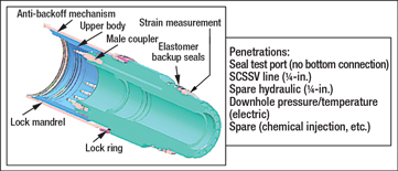
The upper completion was deployed using a hydraulic tubing hanger-running assembly (THRA) run on 5½-in. HT-55 drill pipe. The THRA has a ported slick joint above the hydraulic portion of the tool, which is located across the lower ram cavity of the SID when the tubing hanger is landed in the tubing hanger spool. The slick joint consists of a 7⅝-in.-OD mandrel with a 5-in. minimum ID. The tubing hanger is of a concentric design and incorporates the hanger lock-down mechanism, Fig. 3.
 |
|
Fig. 3. Slim-bore tubing hanger..
|
|
The IWOCS umbilical was clamped to the drill pipe and provided control of tubing hanger and running tool functions while running in hole. The IWOCS umbilical (which has a 2.8-in. OD) is a 13-function hydraulic bundle with two electrical feed-throughs. This was required to accommodate the minimum tubing hanger functions and interfaces to all the downhole lines. The IWOCS umbilical termination assembly and landing string umbilical clamps have a maximum running OD of 13.4 in. to fit within the 13⅝-in. nominal minimum pass-through diameter of the SBOP system.
During a weather-related planned disconnect of the riser from the SID, the 1-in. test line ROV stab was damaged. The steel cable designed to pull the ROV stab parted, thereby subjecting the hose itself to the forces required to pull the ROV stab. The riser offset at the time the hose became taut caused the ROV stab to become side loaded when it was pulled out, further damaging the stab. Repairing this connection was not practical, so the completion team was asked to revise the operational steps to set the packer and test the annulus without the use of the 1-in. line.
The 1-in. test line was added to the SBOP system to address completion operations, specifically for rig floor monitoring of annulus pressures while setting the production packer and testing the tubing hanger from below. With loss of this line, ability was lost to monitor annulus pressures and chart them at surface during packer setting operations; apply pressure below the tubing hanger; equalize across the annulus access valve prior to ROV functioning to the open position; and activate the secondary release of the THRA from the tubing hanger via the 1-in. line.
CONCLUSIONS
The SBOP system safely increased the water depth capability of the Arctic I rig from 3,100 ft to more than 6,200 ft. The well design and drilling/completion functional requirements at Parque das Conchas were found to be well suited to the Arctic I-specific SBOP system.
A planned riser disconnect and reconnect were performed successfully. However, failure of the wire tether attached to the 1-in. hose line stab led to damage to the integrity of the 1-in. hose line during the riser disconnect. The first three horizontal gravel packs were executed successfully despite narrow operating parameters inherent in the shallow Ostra reservoir. The first three upper completions were installed successfully despite the unavailability of the 1-in. test line. 
ACKNOWLEDGMENT
This article was prepared in part from SPE/IADC 119606 presented at the SPE/IADC Drilling Conference held in Amsterdam, March 17–19, 2009. The authors would like to thank the BC-10 co-venturers Petrobras and ONGC for permission to publish this article.
|
THE AUTHORS
|
 |
Brian Tarr is a Senior Staff Well Engineer in Shell’s Houston-based Well Technology group. His area of expertise is surface BOP technology. He has a master’s degree in petroleum engineering from Heriot-Watt University in Edinburgh, Scotland.
|
|
| |
Tor Taklo is a Well Engineering Superintendent for Shell International E&P’s Deepwater Well Delivery division. He holds an MS degree in petroleum engineering from the University of Stavanger in Norway.
|
|
| |
Andrew Hudson, a Senior Staff Production Engineer and Senior Subsea Well Engineer, has worked in Deepwater Projects for Shell since 1983. He attended the University of Wales, where he studied mechanical engineering.
|
|
| |
Lisa Stockwell is a Subsea Completion Engineer based in Shell’s Rio de Janeiro office. She graduated from Tulane University in New Orleans with a BS degree in mechanical engineering.
|
|
| |
Jim Schroeder is Operations Manager–Performance for Transocean, working in Macae, Brazil. He holds a BS degree in mining engineering from the University of Wisconsin-Platteville.
|
|


