A new well testing technology allows fluid collection for analysis, determination of fluid properties at line conditions and pinpointing of dry gas properties, all at the wellsite.
Sergey Romashkin, Rospan International; Vitaliy Afanasyev and Vlamir Bastos, Schlumberger
Multiphase well testing is recognized as state-of-the-art technology for metering oil, gas and water streams without needing to first separate phases. It is particularly effective when measuring transient and volume flows for condensate and heavier oils when traditional meters are less effective. Another benefit is easier deployment to harsh, isolated regions, such as the Siberian gas-condensate field discussed here.
A past challenge of multiphase well testing has been an inability to collect representative fluid samples for real-time compositional analysis. However, a new, highly portable system has been developed that allows collection of such samples and then determines fluid volumetric properties at line conditions along with dry gas properties. Combining these properties can minimize uncertainties that often arise when key fluid parameters are not correctly entered in a multiphase flowmeter’s computation algorithm. Basic Pressure, Volume and Temperature (PVT) measurements can be made at the wellsite. This improves the multiphase flowmeter’s ability to compute flowrates.
NEW METHOD NEEDED IN NORTHERN SIBERIA
Rospan International, operating a series of condensate reservoirs in Siberia, recognized the need for a more thorough understanding of drainage behavior for better field management since, in most cases, the reservoirs previously had been produced below their dew point. Intense drainage from mostly low-productivity wells had resulted in reservoir pressure depletion. Nevertheless, despite such restraints, the reservoirs demonstrated that they could support substantial future production.
In the past, well tests in the region had been conducted with traditional separation equipment, which provided useful information. However, introduction of multiphase flowmetering technology enabled operators to measure steady-state or pseudo-steady-state condensate, water and gas rates, as well as provide the true transient description of multiphase flow. The high-gas volume fraction domain in the region, ranging typically 97–99.5%, called for the high-resolution and stable-measurement chain obtained with the dual-energy, gamma-venturi multiphase flowmeter. However, this made it necessary to capture an accurate set of PVT properties to ensure proper computation of condensate, water and gas rates in the line at standard conditions.
As operator in two license areas amid a very large condensate field, Rospan found it difficult to conduct well tests and interpret data. This was due to complicated reservoir structures, relatively high formation pressures and the physical and chemical properties of the produced fluids, as well as the scarcity of gas condensate well testing services in the region.
The field was discovered in 1966. Total SPE proved and probable reserves were 2.2 billion boe (360 Mcm) of condensate, and 35 Tcf (1 Tcm) of gas. Total Capex over the life of production was estimated at about $1 billion.
The deepest and most productive of the reservoir layers produced in the license areas lies at 3,900–3,970 ft (1,170–1,191 m). Net reservoir pay thickness ranges to 148 ft (45 m) for oil and 197 ft (60 m) for gas. Average open porosity is 15–18%; oil saturation is 60% and gas saturation is 56–77%.
Separator gas rates range from 106–1,060 Mcfd (3–30 Mcmd) through an 8-mm choke to 11.5–12.0 MMcfd (326–339 Mcmd) through a 10-mm choke. Condensate rates range from 2–69 bpd (0.3–11 cmd) through an 8-mm choke to 686–1,320 bpd (109–210 cmd) through a 10-mm choke. Formation pressure varies between 7,680 and 9,570 psi, and formation temperature spans 91–127°C.
In 2003, when the field entered the next stage of development, the operator considered it urgent to review the quantity and quality of data and determine the types of surveys needed to improve depletion control. Without modern well testing technology, it would be nearly impossible to properly identify any contributing or noncontributing formation intervals. That created a challenge to obtaining reliable data quality from separate well flowrate measurements. Also, it was necessary to track down fluid property changes and secure highly accurate bottomhole pressures and temperatures to optimize field management.
Strict new HSE standards, combined with application of reservoir models, created more stringent requirements on well appraisal and evaluation. So, in 2007, the operator surveyed the regional market and issued a tender for all required services.
The company required bidding companies to:
- Provide safe work performance on wells having an anomaly ratio of up to 1.7
- Separate the measurement of rich gas with a condensate content of 100–500 g/cu m
- Conduct flowrate metering without gas emissions
- Take representative gas and condensate samples while obtaining fluid composition, and identify potential liquid condensate content and its recovery factor
- Provide long-term measurements of bottomhole pressure and temperature via extended memory recording
- Demonstrate equipment mobility and high operational performance necessary to sustain up to 30 tests per year.
In essence, the operator was seeking a strategic partner that would meet these and other requirements, including competitive pricing.
TACKLING TOUGH TESTING OBJECTIVES
While each of the bidders could provide certain aspects of the services necessary for gas condensate well testing in the region, the operator decided to make use of one of the bidders’ PVT laboratory analysis capabilities, as well as the special gas condensate field development planning, interpretation and analysis capabilities of another bidder, a Russian institute.
However, in considering the other bids, the operator recognized that an overriding issue involved in the use of conventional separation equipment was that metering devices connected to a single gas- or liquid-phase outlet assume perfect separation for total flow measurement. They assume that the fundamentals of flow measurement are at play.
Obtaining high-quality separation in gassy environments, however, is considerably more challenging due to some unique conditions. Droplets of condensate, for example, may have very low settling velocities, and centrifugal devices compound the problem, always leaving some underlying doubt. Another potential drawback of such devices is their inability to monitor rapid changes in flow created by transient issues such as those encountered during slugging or liquid loading, both of which occur frequently during well testing in the region. Finally, devices such as isokinetic samplers, which collect a mixture of the correct fraction ratio, depend largely on the ability to obtain a truly representative mix of the three flowing phases.
However, conventional testing technology does have benefits. For example, separation devices make large amounts of liquid condensate available in a single-phase “pool.” Isokinetic devices, too, can provide single-phase samples through the use of a small separator that provides monophasic gas and liquid samples while keeping separation pressure as close as possible to flow conditions.
The operator accepted the bid by Schlumberger, which offered a multiphase flowmeter and slickline service that would enable the operator to run and set downhole pressure and temperature recorders. But equally important was addition of a new device for collecting representative samples of each of the three phases without the need for significant separation.
MULTIPHASE SAMPLING DEVICE
The petroleum services industry has long sought ways to obtain reservoir fluid properties while using multiphase flowmetering. At first, attempts were made to collect three-phase samples from multiphase flowmeters and then segregate them in an off-site PVT laboratory for subsequent testing. However, this proved to be cumbersome and required numerous samples to obtain adequate volumes for physical recombination. This was particularly true in northern Siberia, where long-distance shipping is required to get samples to PVT labs.
Due to the complexity of multiphase flow regimes, it may never be possible to sample only one phase at a time. However, there is always a position in the flowline at which one phase is predominant, so the sampling technique must allow selection of this optimum sampling point. Collecting phase samples from the same point and somehow segregating a phase enriched under isobaric and isothermal conditions is required for each phase collected to be representative of flow.
The complex challenge of formation and production fluid evaluation can be resolved with multiphase fluid sampling under line conditions, combined with wellsite fluid analysis using a “kit” such as that used in the Siberian condensate field operation.
Fluid property values also can be obtained successfully by using an Equation-Of-State- (EOS-) based predictive model modified to measure PVT lab data. However, well fluids from a field subjected to lengthy primary development may not have been analyzed previously, or the PVT reports may be too old.
The multiphase flowmetering technology chosen by the operator has a number of advantages over conventional separator sampling. These include:
- Upstream/downstream applications
- Higher pressures/temperatures (10,000 psi/150°C)
- Accurate Gas-Liquid Ratio (GLR) monitoring during sampling
- Wellsite data availability for quality control.
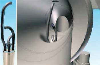
The PhaseSampler multiphase sampling device is fitted with three sampling probes that are positioned across the flowpath, Fig. 1. This enables them to collect discrete, phase-concentrated samples at line conditions. Two probes are placed at the top and bottom of the pipe, respectively, with one facing the upstream flow to collect a majority of liquid, and the third, located at the center of the pipe, facing downstream to collect the gas.
 |
|
Fig. 1. Schematic of sampling probes.
|
|
The “undesired” phase from the sampling device is displaced with a piston that is activated by monitoring the displacement with a phase detector (a modified optical probe) and selecting the desired probe at the manifold.
The hardware involved includes a multi-probe sampling device that retrofits to the liquid sampling port on the flowmeter, an optical phase detector to sense the type of fluid entering or leaving the sample chamber, a wellsite fluid property measurement kit that allows direct measurement of key fluid property inputs at line and standard conditions for any type of multiphase flowmeter, and dedicated data acquisition software that receives the measured fluid properties, as an alternative to the correlation available with standard multiphase meters.
The hardware addresses sampling and thermodynamic equilibrium issues in several ways. The multi-probe sampling component is inserted through the liquid sampling trap and into the multiphase flowmetering stream. This produces good mixing due to a venturi located in front of each probe. As mentioned earlier, the samples are taken at the same point, which ensures that the pressure and temperature are constant and the samples refer to the same thermodynamic equilibrium.
The device also has the capability of enriching any desired phase during the sampling process. If a specific phase exists in a very small fraction inside the flow, the sampler can actively enrich it so that it captures a large enough volume for all required measurements.
In addition, the pressure and temperature are maintained through heating and insulation during the sampling, segregation and enrichment processes to ensure that there is no mass transfer between the phases. And finally, using the optical phase detector, the device is designed to verify that the correct phase has been captured or transferred.
Since the sampling device can be placed at different positions and directions in the flowline, it can capture a predominant phase and does not depend on flow type (gas, oil and water) and/or flow regimes (mist, bubble, slug, churn flows, etc.).
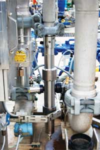
While the device captures all basic measurements, it involves a minimal array of equipment, Fig. 2. Gas gravity, for example, is measured through use of a portable gas chromatograph, and oil viscosity and atmospheric density also are determined by portable equipment. Indirect measurements of oil and water phase densities are achieved by a flash technique after measuring Gas-Oil Ratio (GOR), volume factors, shrinkage, gas expansion and other data. Formation and production fluids evaluation yields full wellstream fluid properties, including physical recombination and composition in the multiphase environment.
 |
|
Fig. 2. Multiphase sampling device mounted in the flowmeter.
|
|
The new wellsite system delivers multiphase metering and sampling, physical recombination and saturation, a phase behavior package based on EOS, bottomhole sampling and pressure/temperature measurements conveyed by slickline.
PHYSICAL VS. MATHEMATICAL RECOMBINATION
The likelihood of obtaining initial formation fluid as a result of recombination depends on reservoir conditions, well parameters, the samples collection procedure and the recombination method used, among other conditions.
Physical recombination requires three main inputs—gas, liquid and GOR—which are physical samples and measurements made by multiphase flowmetering. It is carried out using the tool “kit” supplemented with the sampling device. The sampling cylinder usually is used as the recombination cell.
Mathematical recombination, on the other hand, requires more information, including the density of the liquid at recombination conditions, the molecular weight of the liquid/gas expansion factor, and the composition and ratio of the liquid and gas.
Using physical recombination has significant advantages, since it delivers a tangible result—a monophasic sample. And while mathematical recombination involves greater time and personnel costs, it reduces uncertainty coming from the calculations, opens opportunity for full analysis, and captures experimental reference points like saturation point and live fluid densities.
Both types of recombination use the GLR as a key input, selected from the flowmeter report and properly applied. For quality control, there are two options for collecting the GLR using PVT properties. It can be back-propagated from bottomhole formation fluid samples if available, using EOS or a separator test in the PVT laboratory, or it can be checked afterward by comparing the dew point of recombination with bottomhole flowing pressure, particularly in the case of monophasic bottomhole flow.
In any case, the most valuable result of recombination is a formation fluid model that can be used during the exploration, development and production of the field and also is an excellent tool for forecasting.
RESULTS
The operator contracted for a comprehensive well test campaign using Schlumberger’s multiphase flowmeter equipped with the multiphase sampling device. The testing began in May 2007. At least two sets of samples were captured in sampling cylinders for each well, and all sample sets were validated and used for wellsite analysis. Basic phase properties required for multiphase flowmeter computations were provided. These included oil density and shrinkage at line conditions, GOR, stock tank oil density and viscosity, gas density, expansion coefficient, the Z-factor at line conditions, composition of stock tank gas, water density and shrinkage at line conditions, GWR, water viscosity and density at standard conditions.
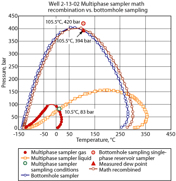
In the first case, multiphase samples were taken at the 6-mm choke on Well 2-13-02, from which BottomHole Samples (BHSs) were recombined mathematically. The BHS was sampled in a single-phase reservoir sampler at the bottom of the production tubing. Since the sampling pressure was higher than the detected dew point, monophasic flow was assured. This flow entered the tubing and then split into two phases on the way to the multiphase flowmeter, where they were captured by the sampling device. Samples were quality controlled, studied and recombined mathematically using the GLR averaged over the sampling period.
Figure 3 graphs the multiphase sampling device sample phases, mathematically recombined, over BHS phase envelopes. For reference, it also shows bottomhole and surface sampling conditions. The envelopes of the multiphase samples cross over at the sampling points, indicating that condensate and gas represent phases passing through the multiphase flowmeter in thermodynamic equilibrium. The composition of the single-phase BHS was obtained with wellsite analytical instruments used in EOS to obtain the BHS phase envelopes (blue curve). The best-fit characterization brought the phase diagram closer to the measured dew point (orange triangle).
 |
|
Fig. 3. Case study 1, mathematical recombination.
|
|
The same characterizations were applied to a mathematically recombined monophasic sample. Its phase diagram in Fig. 3 (red curve) shows a remarkable consistency with the bottomhole diagram. This indicates that the samples were good as initial material for recombination, and that the recombination GLR was suitable for reconstructing monophasic flow. It also demonstrates that the EOS works well vs. the experimental reference point with properly selected characterizations, and the whole process of sampling, quality control, recombination and modeling is consistent and capable of solving the major challenge—formation fluid simulation.
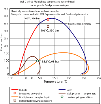
In the second case study, which was the first physical recombination, two studies were conducted to validate samples from Well 2-05-03 with the multiphase sampling device and their subsequent mathematical recombination, to estimate the dew point for a later multiphase sampling experiment.
Using a set of wellsite analytical equipment combined with sampling device accessories, the crew performed physical recombination. Afterward, they conditioned a monophasic sample for one day under reservoir conditions, and then transferred a 25-cc portion of the sample to a PVT cell to determine quality control and saturation pressure.
As indicated in Fig. 4, the lowest expected dew-point pressure was 4,786 psi, the bottomhole flowing pressure during sampling. The higher dew-point pressure depicted, however, was due probably to some mechanical gas lift of liquid deposits. But the experiment gave dew at 5,465 psi, which confirmed the EOS prediction based on mathematical recombination. The successful physical recombination confirmed that using samples from the multiphase sampling device was feasible and applicable. Physical recombination also was easier to perform than conventional recombination of separator samples. Additionally, the physical recombination vs. bottomhole flow data confirmed the well’s flowing regime.
 |
|
Fig. 4. Case study 2, physical recombination.
|
|
While some aspects of the sampling and analysis program are still being investigated, this new technology appears to bridge the gap in fluid sampling in the multiphase flow environment. It also adds analytical techniques to replace methods for obtaining fluid properties during production well tests. Regular and systematic application of the technology provides comprehensive knowledge about formation fluid and gives operators the basis for prediction of fluid properties and composition changes over the lifetime of a field. It also can perhaps be expanded into new applications and opportunities, offering multi-segment services to optimize well tests. 
ACKNOWLEDGEMENT
This article was prepared from SPE 115622 presented at the SPE Russian Oil & Gas Technical Conference and Exhibition held in Moscow, Oct. 28–30, 2008.
|
THE AUTHORS
|
| |
Sergey Romashkin is head of reservoir management for Rospan International, TNK-BP, Russia. He started as a Production Operator, then was Field Geologist and Leading Specialist for reservoir management. Mr. Romashkin’s work focuses on creating an up-to-date data bank of geological production and field development project information, well testing using multiphase flowmeters equipped with multiphase sampling devices, and field testing of selective well fracturing. Mr. Romashkin earned an engineering diploma in E&P for gas and gas condensate fields from Tyumen State Oil and Gas University.
|
|
| |
Vitaliy Afanasyev is a Testing Project Manager in Noyabrsk, Russia, for Schlumberger, a position he assumed in January 2009. The project he leads includes construction of a full-scale PVT laboratory for the Russian oil and gas condensate industry. Prior to this, he served as an Engineer in charge of fluid sampling and analysis operations in North Siberia. Mr. Afanasyev joined Schlumberger as a Field Engineer in 2005. He earned an engineering diploma and then obtained a candidate of technical science degree at Ufa State Aviation Technical University.
|
|
| |
Vlamir Bastos is Brazil Testing Marketing Manager for Schlumberger, a position he assumed in January 2009. Prior to this, he served as the PhaseSampler product champion in the Schlumberger France Product Center in Clamart. Mr. Bastos joined Schlumberger as a Field Engineer in 1999. Since then he has held positions in Testing Services and as a Field Engineer Recruiter. He earned a BS degree in mechanical engineering (production) from Escola Federal de Engenharia de Itajuba, Brazil.
|
|
| |
|


