Planning optimal casing points
Vol. 230 No. 6 SPECIAL FOCUS: DRILLING AND COMPLETION TECHNOLOGY Planning optimal casing points A new algorithm and program were used to plan casing points in Persian Gulf wells. Rasool Khosravanian, M. B. Aryanezhad, Seyed J. Sadjadi and Farnaz Barzinpour
A new algorithm and program were used to plan casing points in Persian Gulf wells.Rasool Khosravanian, M. B. Aryanezhad, Seyed J. Sadjadi and Farnaz Barzinpour, Iran University of Science and Technology; Bernt S. Aadnoy, University of Stavanger; and Abbas Naderifar, Amirkabir University of Technology, Tehran
Determining optimal casing point locations is a challenging task since many engineering and geologic variables affect each other and are often non-linear. A new mathematical formulation and procedure for optimizing casing string placement was used in a study on the application of non-traditional optimization techniques, namely, Simulating Annealing (SA), to determine near-optimum casing points of wells in a case study of South Pars gas field in the Persian Gulf in Iran. The model is applied to the practical design of the wells, and numerical results illustrate its accuracy and efficiency. INTRODUCTION Determining optimal casing point locations has a potentially high economic impact. Finding these optima depends on a complex combination of geological and petrophysical factors, flow regimes and economic parameters. Well design and casing setting depths are important factors that were taken into consideration. This work is based on the geometric “need” of wells. A well’s geometric need consists of maintaining a linear and non-linear path at the well segment. The value of the inclination, azimuth angle, etc., should be set in the given threshold value, and it has capabilities to accommodate any eventualities that come in the course of drilling. Casing costs comprise a relatively large portion of a well’s budget (up to 30%), and the impact of casing selection points on the overall well costs can be significant. A drilling engineer’s main task is to develop a plan to be optimized within certain economic and operational limits. The solution involves two main elements: well cost estimation and geological conditions. Each of these elements represents a wide set of decision variables, and the choice of their weight and values is an optimization problem. It is not feasible to consider all decision variables and all possible combinations. Our objective is to formulate a program considering safety, cost minimization and usability. It is not always possible to accomplish all of these objectives in each well due to constraints based on geology, drilling equipment, casing limitations, hole sizing or budget. In this article, we attempt to balance the constraints with each other. STATEMENT OF THE PROBLEM Conventional design often dictates that very large surface casing be used to allow the passage of many subsequent casing strings, telescoping down in size, required to reach and penetrate target zones. The larger the casing, the larger the surface facilities needed to handle it and the greater level of services needed to support drilling and completion of these larger holes, thus increasing exploration and field development costs significantly. The well in this study has been divided into the components shown in Fig. 1. The well consists of the Kick-Off Point (KOP), three turn sections, two hold sections, a straight section and the target. The KOP can be fixed by the user or it can be optimized by the model. Each turn section can be used for both build and change in azimuth. We assume that the well is vertical to the KOP.
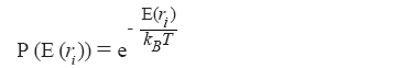
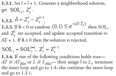
MATHEMATICAL OPTIMIZATION Two steps are required for the formulation of this optimization problem. First, the system must be identified. All data related to the well should be collected and considered. Design variables—design data, surface and target coordinates, post analysis data, etc.—must be collected. Decision variables such as casing depth must be established to characterize the problem, and system constraints should be recognized. Second, an optimization procedure requires the characterization of the function to be optimized (minimized or maximized), known as the objective function. In this study, the output, or objective function, is often measured in terms of total depth of the well. Annealing analogy method. The application of SA to casing point selection can be divided into nine steps: 1) receive the input from the well design module; 2) enter three simulated-annealing parameters; 3) define the design chromosome representing the problem; 4) generate the random initial design “chromosome”; 5) decode the design chromosome into a real number; 6) apply constraints; 7) apply an objective function and a fitness value; 8) implement the annealing schedule by the Boltzmann probability; and 9) set the cooling rate and criterion for termination. Simulated annealing is based on an analogy to the cooling of heated metals. In any heated metal, sample the probability of some cluster of atoms at a position, ri, exhibiting a specific energy state, E(ri), at some temperature, T. It is defined by the Boltzmann probability factor: where kB is Boltzmann’s constant. As a metal is slowly cooled, atoms will fluctuate between relatively higher and lower energy levels and equilibrate at each temperature. Application of the annealing strategy to any engineering optimization problem requires definition of four major components: Problem configuration: the suitable domain over which the optimum can be sought. This is often expressed in the form of constraint equations. Neighborhood configuration: a method of iteratively perturbing the design vector to create new trial points. Objective function: a scalar equation that weighs all of the design variables to provide a measure of the goodness for each trial point. Cooling/annealing schedule: a method for specifying the maximum number of inner loop iterations and the manner in which the control parameter will be decremented in each iteration of the outer loop. SA loop. To create your program, first initialize the iteration counter: i =0, temperature Ti =T0. Generate an initial solution. Let the best solution be represented by SOLbest and the best objective value by Zbest. Assign initial operation assignment SOL0 to SOLbest and initial objective value Z0 to Zbest. Then execute the following steps: 1.0. Execute outer loop—i.e., steps 1.1–1.7—until conditions in step 1.7 are met.
1.3. Execute inner loop-—i.e., steps 1.3.1–1.3.4—until conditions in step 1.3.4 are met.
1.4. Set: i = i + 1. 1.5. Update
1.6. Reduce the cooling temperature: 1.7. If one of the following conditions holds true— 2.0 Print the best solution obtained and terminate the procedure. Determining good annealing parameters for a given problem is often a hard task and needs experimentation. The following values for the SA parameters were selected after experimentation:
Mathematical formulations. Solving the problem of well-path planning as an optimization problem requires the definition of an optimal criterion. The optimization criterion is any well-defined objective function whose minimum is sought, subject to the equality and inequality constraints discussed. Several criteria or combinations of criteria may be used. The measured depth objective function is expressed in the system variables as following: CASE STUDY OF SOUTH PARS FIELD South Pars Field, discovered in 1990, is located some 100 km offshore Iran in the Persian Gulf and extends into neighboring Qatar, where it is known as North Field. Main gas-bearing formations in the field are the Upper Permian and Lower Triassic carbonate series and Early Silurian dark shales. South Pars has a 25-phase development plan spanning 20 years. Field geology. An appraisal well was initially drilled in South Pars in 1990 and encountered gas reservoirs in Upper Permian and Lower Triassic carbonates. The field has 441.5 Tcf of proved reserves and together with its Qatari extension, North Field, has 900.5 Tcf of gas in place and forms the world’s largest non-associated gas field. Gas accumulation in the field is mostly limited to the Permian–Triassic stratigraphic units that became prospective during the 1970s following delineation of enormous gas reserves. These units, known as the Kangan–Dalan Formations, constitute extensive gas reservoirs in the field and Persian Gulf area, which are composed of carbonate-evaporite series formerly known as the Khuff Formation. Generalized Permian–Triassic stratigraphy of South Pars Field is shown in Fig. 1. Accordingly, Permian–Early Triassic has been divided into Faraghan (Early Permian), Dalan (Late Permian) and Kangan (Early Triassic) Formations. The Faraghan Formation consists of an alternation of sandstone, shale and limestone. Based on paleontological data and some foraminifer species, this formation has been assigned to the Early Permian. The Faraghan Formation is overlain by the Dalan Formation and rests disconformably on the Devonian sandstone Zakeen Formation. The Dalan Formation has been assigned to the Late Permian and subdivided to three members, Lower Dalan, Nar and Upper Dalan from bottom to the top. This formation, which rests disconformably on the Faraghan Formation, is overlain by the Kangan Formation. The Dalan Formation is more than 680 m thick and mainly consists of limestone (Lower Dalan), anhydrite and subordinate dolomite (Nar Member), and limestone, dolomite and subordinate dolomitic limestones (Upper Dalan). The Kangan Formation has been assigned to the Early Triassic. This formation in South Pars Field is nearly 193 m thick and consists of limestone, dolomite, anhydritic dolomite and thin shale layers from bottom to top. The Kangan Formation is sealed by the Triassic sedimentary Dashtak Formation, which is an efficient cap rock. Drilling program. The following drilling program was carried out for the wells with a jackup unit:
With an optimization procedure, users can focus attention on real-world issues and allow issues associated with optimization to be handled mathematically. The user inputs the target coordinates and allowable tolerances within which the target may be reached. The constraints on each of the parameters are chosen that reflect physical, operational or geologic constraints on turn rates, hold sections, etc. As mentioned earlier, an SA algorithm program that implements the above optimization procedure for a three-turn profile has been developed. Results. The resulting non-linear optimization problem is solved using SA design. The SA procedure is robust, efficient and superior to trial-and-error heuristic techniques. Non-linear optimization is a powerful and versatile mathematical tool that can be used for planning optimal casing points and can be extended to several other wells that will be drilled in South Pars Field in the future. If changes in the well plan were necessary, the user could change the preferred values or change the minimum and maximum ranges to calculate a more desirable well plan. SA algorithms take the casing setting depths into consideration, unlike the commercially available package such as WELLDES, which does not. Table 1 describes the optimum casing points for 133⁄8 in., 95⁄8 in. and 5 in. It is noteworthy that casing points for 32 in. and 24 in. were fixed by the company; therefore, we ignored them for optimizing. Figure 2 shows safe and economic casing points for Well SPD-01 based on the proposed model.
This model optimizes well costs by managing the well design, especially casing points, better than selecting them by the traditional method. Figures 3 and 4 show that the new model is capable of reducing the time and cost of a drilling operation for different wells in South Pars Field. This new approach to well design has the potential to reduce drilling time by significantly reducing the average well spent time from 43 days with the old plan (Avg. old) to 38.15 days with the new plan (Avg. new), Fig. 4.
Conclusions were formulated based on the analysis of the results obtained for the mentioned wells by applying commercial software. If we apply only WELLDES, we get the worst results. Moreover, the SA methods give better results. The values in Table 2 show that the CPU time is better in the SA algorithm compared to other programs.
CONCLUSION Mathematical modeling was applied to the optimization of casing point selection and simulated annealing algorithms were successfully applied to South Pars Field. The results of the study show that the new method has significant potential to increase efficiency and reduce cost and time. The SA algorithm proved to be a desirable approach for optimal well design in comparison to older methods. Comparison between the SA algorithm, Matlab software and the WELLDES program confirmed the validity of the SA algorithm. ACKNOWLEDGMENT The authors gratefully acknowledge National Iranian Oil Company for its cooperation and support of this project. NOMENCLATURE T1, T2, T3: Dogleg severity of different portions, degrees per 100 ft.
BIBLIOGRAPHY Aadnoy, B.S., “Casing point selection at shallow depth,” Journal of Petroleum Science and Engineering, 6, 1991.
|
|||||||||||||||||||||||||||||||||||||||||||||||||||||||||||||||||||||||

 .
.


- Coiled tubing drilling’s role in the energy transition (March 2024)
- Oil and gas in the Capitals (February 2024)
- Using data to create new completion efficiencies (February 2024)
- Digital tool kit enhances real-time decision-making to improve drilling efficiency and performance (February 2024)
- E&P outside the U.S. maintains a disciplined pace (February 2024)
- U.S. operators reduce activity as crude prices plunge (February 2024)

