Real-time monitoring, simulation, 3D visualization and diagnosis help drillers anticipate problems.
Rolv Rommetveit and Sven Inge Ødegård, eDrilling Solutions; Knut Steinar Bjørkevoll, SINTEF Petroleum Research; and Mike Herbert, ConocoPhillips Norge
This article demonstrates use of an advanced flow model for real-time supervision and control of Equivalent Circulating Density (ECD) and ECD-related effects. This system, eDrilling, allows real-time drilling simulation, 3D visualization and control from a remote-drilling expert center. The concept uses all surface and downhole Real-Time (RT) drilling data in combination with RT modeling to monitor and optimize the drilling process, while visualizing the wellbore in 3D.
REAL-TIME MODELING
The key elements of the system are a) RT simulation and visualization in a virtual wellbore and b) decision support. The infrastructure allows for simulation of drilling sub-processes using integrated drilling models driven by the process itself. This RT-enabled integrated drilling simulator creates a “mirror” of the drilling process, providing information on key drilling parameters: hydraulics profile (ECD), temperature profile, friction conditions along the drillstring and wellbore, cuttings transport conditions, well instability tendencies, pore pressure ahead of the drillbit and optimal ROP. The system also makes automatic diagnoses of potential drilling problems by combining RT simulations with drilling data.
The virtual wellbore shows the drilling status of the bit, drillstring, BHA, etc., allowing visual communication of the well’s status across professional boundaries (drilling, geology, asset team) during the drilling operation.
DATA QUALITY
Because models need good input data for accurate and reliable results, data quality from external sources is important. Quality is addressed by improving data sources and signal transmission, by filtering invalid data and by correcting data before it is used. The last two points are addressed by a dedicated Data Quality Module (DQM) that corrects input data.
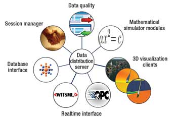
The Data Distribution System (DDS) is the kernel for the system’s data distribution. Users can subscribe and publish data to the DDS server with external data being published into the server by interface clients. At the Ekofisk pilot, OPC and ODBC servers handled this. WITS data from Halliburton (Sperry Sun) were fed into the system via OPC, and Peleton WellView data were fed into the system via the ODBC. In the near future, the DDS system will have DDS-enabling WITSML communication, Fig. 1.
 |
|
Fig. 1. DDS is the kernel for the system’s data distribution.
|
|
3D VISUALIZATION
The 3D visualization engine has the capability to import models with high complexity, and then fly (zoom) into subsurface details. Typical examples include platform complexes, rig configurations, drilling equipment and other details.
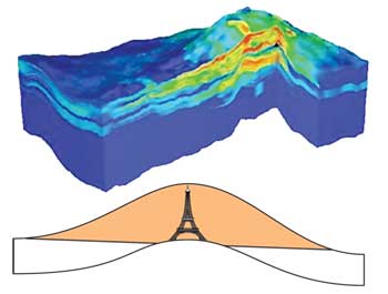
Ekofisk Field in the North Sea was found in 1969, and produced 2.1 billion bbl of oil and 124 Bcm of gas by 2004. Average production is 350,000 bopd and 350 MMcfgd with water injection of 900,000 bpd. The thickness of the Ekofisk reservoir is similar to the height of the Eiffel tower, Fig. 2.
 |
|
Fig. 2. Ekofisk reservoir thickness is similar to the Eiffel tower’s height.
|
|
The system allows the user to track geology by showing the rock layers as equipment passes through different formations. The system displays all relevant information including the bit’s location as it passes through the BOP and casing.
DRILLING EXPERIENCES
The well example is a sidetrack from the main wellbore. The operational sequence covered is to drill out the shoe track and continue to drill into the reservoir. This covers three days of operations during Sept. 2–5, 2007. The drillstring included an 8½-in. x 9½-in. rotary steering assembly in combination with a formation pressure tester and MWD pulse telemetry system.
Oil-based mud was in the borehole at 14.7 ppg at the beginning of the task. This mud was displaced with 9.5-ppg mud at the beginning of this operation. Mud density fell slightly during the operation and was later increased, first to 10 ppg and later 10.2 ppg. Inclination angles for this section were stable around 9° with a slight swing in azimuth to the right.
Many problems were encountered with this well, before, during and after this section. Problems included mud loss, gas influx, tight hole and equipment failure.
An advanced pressure and temperature model, optionally with automatic or semi-automatic calibration, runs continuously during drilling operations and converts raw data to useful information.1–7
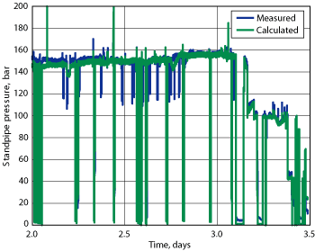
Figure 3 shows flow model results when replaying data from the Ekofisk well through the system. A drilling and reaming sequence of 1.5 days is shown. The decreases and increases in pressure after 3.1 days are due to mud density increases.
 |
|
Fig. 3. Flow model results from the well matched standpipe pressure, when the data was replayed through the system.
|
|
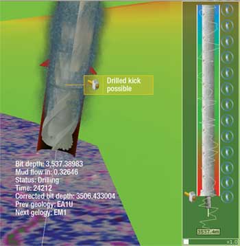
In this sequence, the model reproduced variations accurately without continuous tuning; only a constant 10% correction was applied. There is some deviation between model and data shortly after 2.75 days, most likely due to inaccurate information on mud density changes. The good match with measured standpipe pressure supports the calculated bottomhole Equivalent Mud Weight (EMW). The model also calculates ECD at other positions along the open hole, and the result is compared to the most recent collapse, pore and fracture pressure available. The 3D view can then warn operators and engineers when they are getting close to or outside borders, Fig. 4.
 |
|
Fig. 4. The 3D view warns operators when they are getting close to borders; low ECD indication is in red.
|
|
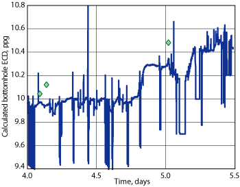
Pressure points measured while drilling are added in Fig. 5. Gas return was observed in this period, and mud density was increased several times, which seems consistent with the fact that some pressure points are above calculated EMW. With an accurately forecasted pore pressure profile, the system gives early warnings on these events.
 |
|
Fig. 5. The system monitors ECD versus pore and fracture pressure, giving a warning when limits are exceeded.
|
|
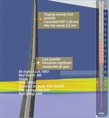
The system monitors the ECD versus pore and fracture pressure profile, giving a warning when these limits are exceeded. In Fig. 5, the relative ECD versus relative pore pressure is shown. The mud density was increased twice to combat kick indications. The system detected problems early, and gave a warning that a kick was possible, Fig. 6. Losses were also detected by the diagnosis system earlier than with the normal procedures.
 |
|
Fig. 6. Mud density detection gives early kick warnings.
|
|
The system also gave warnings on hole cleaning problems. Some time later, the drilling had to be halted to circulate the hole clean of cuttings.
VIRTUAL PWD
In a later well, there were problems with the MWD during a crucial phase of drilling due to tool failure. This resulted in a one-day delay to pull out of the hole. The system had accurate real-time simulations running throughout. Calculated properties had been verified against measured values before tool failure, and the static calculations were very accurate. The dynamic calculations suffered slightly from configuration data of varying quality, but the deviation was constant. So the ECD calculations from the system could have been used as a “virtual pressure-while-drilling” tool, and one trip could have been saved if the system had been trusted. This extra trip cost NOK3 million ($600,000).
PROBLEM DIAGNOSIS
The availability of RT-enabled advanced models and methods prepares the way for a much more robust and reliable diagnostic system. The following sub-systems have been implemented as integrated parts of the system:
- Early kick and loss warning
- Improved volume monitoring
- Improved hole cleaning monitoring
- Improved detection of impending stuck pipe and early detection when going stuck
- Improved ROP monitoring.
The benefits of this system include earlier warnings, more reliable warnings (i.e., fewer false alarms and fewer real events with no alarm) and continuous focus on the process through tedious periods that are considered low risk by the drilling crew.
CONCLUSIONS
A comprehensive system with multiple models and a 3D visualization application, integrated with live drilling data in real time, has been developed and demonstrated on data from real wells. An immediate benefit of the system is easy access to very advanced modeling for the drilling crew and experts who monitor operations from onshore or on the rig.
Dynamic flow modeling shows how a slightly calibrated model gives an accurate picture of openhole pressure. This can be automatically compared to expected collapse, pore and fracture pressure in the openhole section.
The automatic diagnosis system has proven to give reliable and useful messages for ECD monitoring, volume control, losses, early kick detection/warning and hole cleaning problems.
Finally, the system has proven that it can function as a virtual pressure-while-drilling tool when a PWD tool malfunctions or is not used. 
ACKNOWLEDGEMENTS
The authors thank ConocoPhillips Norway and their PL018 co-venturers: Total E&P Norge AS, Eni Norge AS, StatoilHydro ASA and Petoro AS. We also thank the Norwegian Research Council’s Petromaks Program for supporting the development of the eDrilling system and the SFI Center for Integrated Operations in the Petroleum Industry is for supporting this work.
LITERATURE CITED
1 Petersen, J., Bjørkevoll, K. S., Frøyen, J. and R. Rommetveit, “A general dynamic model for flow related operations during drilling, completion, well control and intervention,” IBP 1373_06 presented at the Rio Oil & Gas Expo and Conference, Rio de Janeiro, Sept. 11–14, 2006.
2 Syltøy, S., et al.,: “Highly advanced multi-technical MPD concept extends achievable HPHT targets in the North Sea,” SPE 114484 presented at the 2008 SPE/IADC Managed Pressure Drilling and Underbalanced Operations Conference and Exhibition, Abu Dhabi, UAE, Jan. 28–29, 2008.
3 Bjørkevoll, K. S., Rommetveit, R., Rønneberg, A. and B. Larsen, “Successful field use of advanced dynamic models,” IADC/SPE 99075 presented at the IADC/SPE Drilling Conference, Miami, Fla., Feb. 21–23, 2006.
4 Bjørkevoll, K. S., Molde D. O., Rommetveit, R. and S. Syltøy, “MPD operation solved drilling challenges in a severely depleted HP/HT reservoir,” SPE 112739 presented at the SPE/IADC Drilling Conference, Orlando, Fla., March 4–6, 2008.
5 Eck-Olsen, J., Pettersen, P. J., Rønneberg, A., Bjørkevoll, K. S. and R. Rommetveit,“Managing pressures during underbalanced cementing by choking the return flow: Innovative design and operational modeling as well as operational lessons,” SPE/IADC 92568 presented at the SPE/IADC Drilling Conference, Amsterdam, Feb. 23–25, 2005.
6 Bjørkevoll, K. S., Rommetveit, R., Eck-Olsen, J. and A. Rønneberg, “Innovative design, operational modelling and lessons learned for pressure management during underbalanced cementing with choked return flow,” presented at the Offshore Mediterranean Conference and Exhibition, Ravenna, Italy, March 16–18, 2005.
7 Rommetveit, R. et al., ”A novel, unique dual gradient drilling system for deep water drilling: CMP, has been proven by means of a transient flow simulator,” IBP 1400-06 presented at the Rio Oil & Gas Expo and Conference, Rio de Janeiro, Sept. 11–14, 2006.
|
THE AUTHORS
|
 |
Rolv Rommetveit earned an MSc in physics and a PhD in applied mathematics. He has more than 25 years of experience with drilling modeling, well and pressure control, automated and integrated drilling systems and managed pressure drilling. He has authored more than 60 technical papers and has served as a committee member for the SPE/IADC Drilling Conference and SPE/IADC MPD & UBD Conference. Rommetveit is Managing Director for eDrilling Solutions AS.
|
|
| |
Sven Inge Ødegård earned an MSc degree in cybernetics from the University in Stavanger. He has been working with drilling control and information systems for the last 15 years with experience from large newbuilds like Troll. For the last three years, he has had responsibility for data integration and custom installations. Ødegård is Business Development Manager for eDrilling Solutions AS.
|
|
| |
Knut Steinar Bjørkevoll earned a PhD in theoretical physics and has 17 years of experience in advanced mathematical models for drilling operations. His main focus has been using of integrated models for decision support and automation, including managed pressure drilling in the North Sea. Bjørkevoll is Research Director in the Drilling and Well Construction department within SINTEF Petroleum Research.
|
|
| |
Mike Herbert earned a degree in oceanography and maritime studies. With a background in drilling and real-time operations, he leads a strategy group for integrated operations and real-time reservoir management in OG21, and is responsible for the Onshore Drilling Centre in Norway. Herbert is the Integrated Operations Advisor for ConocoPhillips Norge.
|
|
| |
|


