Low-solids, non-dispersed drilling fluid, hydraulics modeling and engineered sweeps save $500 thousand on a South Texas well.
B. Slusher, Mestena Operating, Ltd.; J. Oglesbee and A. Villarreal, Halliburton
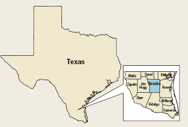
Taking an engineered approach to lost circulation issues helped eliminate the need for a 7-in. intermediate string on the Mestena Operating, Ltd. La Presa 5 well in Brooks County, Texas, Fig. 1. Two offset wells with similar profiles had lost the battle to severe lost circulation in the Vicksburg sandstone, requiring the operator to routinely factor in $500,000 per well for intermediate casing.
 |
|
Fig. 1. The La Presa No. 5 well was drilled in Brooks County, Texas.
|
|
The two offset wells, drilled with the same rig using conventional lignosulfonate drilling fluid, were planned with 95/8-in. surface casing at around 3,000-ft MD, a contingency intermediate string at about 7,000 ft to case off the Vicksburg thief zone, and a target depth of about 8,500 ft. Severe to total lost circulation and differential sticking-common problems in South Texas drilling operations even on relatively shallow wells-plagued the La Presa wells.
A proposal was made by the drilling-fluids company to change the fluid type, flow rate and lost circulation treatments. The three recommended changes were made in an attempt to minimize the Equivalent Circulating Densities (ECD) and match the Lost Circulation Material (LCM) more exactly to the Vicksburg sand’s characteristics.
CLEANER FLUID, LOWER ECDS
The first consideration in reducing lost circulation risk was drilling-fluid selection. Drilling with a fluid that contained minimal solids concentration would help reduce ECD and a fluid with shear-thinning characteristics would exert significantly less pressure on the wellbore when breaking circulation. To aid in stuck-pipe prevention, the ideal fluid would develop a thin, flexible wall cake that could deliver good filtration control, while creating a lubricious layer across the wellbore wall.
Lowering the drilling fluid’s solids content required two approaches: first, a reduction in commercial solids added (e.g., bentonite) and, then, an effective treatment for flocculating and encapsulating drilled solids for easy removal at the surface. The mud density at TD in the La Presa Field ranged from 12.0 ppg on the La Presa 5 to 12.6 ppg on the La Presa 2. Fluids at these relatively low densities typically have a high amount of available free water and drill solids can readily disperse and degrade, creating more solids surface area to be treated, without having a significant effect on the fluid rheology. Therefore, any flocculation and encapsulation additives would need to work aggressively to prevent recirculation and further degradation of fine solids.
The operator selected a Low-Solids, Non-Dispersed (LSND), fresh-water system based on its effectiveness in facilitating solids removal at the first pass over the shaker screens. The LSND system required only a minimal amount of commercial bentonite. A polymeric bentonite extender provided enhanced suspension properties for both the active system and the sweep program. A small concentration of powerful non-ionic polymer was used to inhibit reactive shales and flocculate any fines that entered the system. As a result, the fluid’s native clay content was held to a minimum, which was expected to help the operator achieve the desired ROP, while reducing lost-circulation risk. The LSND fluid was also free of the black-powder thinners used to control rheological properties in a conventional lignosulfonate mud, resulting in much lower dilution rates.
HYDRAULICS MODELING
On the La Presa 5, a 14.0 ppg leak-off test was established at the surface casing shoe at 3,030 ft. The hydraulics profiles of previously drilled wells confirmed that, while the drilling-fluid density and rheological properties had been generally acceptable, modifying the pump rates could offer opportunities to optimize drilling efficiency through potential loss zones.
Using proprietary hydraulics modeling software, technical personnel for the drilling-fluids service company prepared scenarios to demonstrate the effects of various pump rates and ROPs on hole-cleaning effectiveness and ECD at 6,280 ft. Assuming an average cuttings diameter of 0.25-in., the outcome of all the “What if?” hydraulics models showed that cuttings loading would not exceed the safe zone of 3%, by volume, in the annulus.
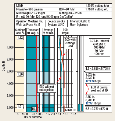
The next step was selecting the profile that would deliver maximum ROP without pushing ECD beyond acceptable limits. Using a surface mud density of 12.2 ppg, the hydraulic models were run at both 50 ft/hr and 90 ft/hr at a pipe rotation speed of 120 rpm. The lowest pump rate modeled was 300 gpm, but there were concerns that this low rate would impair bit performance. The increased cuttings loading-while staying under the 3% limit-pushed the modeled ECD to nearly 0.2 ppg above static density; the highest increase among the four modeling runs at this depth, Fig. 2.
 |
|
Fig. 2. At 300 gpm and 90 ft/hr the hydraulics prediction with increased cuttings loading pushed the modeled ECD to nearly 0.2 ppg above static density.
|
|
The 400-gpm run using an ROP of 50 ft/hr resulted in a slight increase in ECD equivalent to 0.05 ppg at the casing seat and 0.066 ppg at 6,280 ft, Fig. 3. Cuttings loading was minimal, but the reduction in ROP was significant.
 |
|
Fig. 3. At 400 gpm and 50 ft/hr the hydraulics prediction increased the ECD slightly to 0.05 ppg at the casing seat and 0.066 ppg at 6,280 ft.
|
|
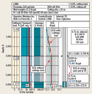
Raising the pump rate to 528 gpm and pairing this flowrate with a 90-ft/hr ROP put ECD at 0.1-0.104 ppg, Fig. 4. The second highest cuttings loading percentage was observed in this modeling run.
 |
|
Fig. 4. At 528 gpm and 90 ft/hr the hydraulics prediction raised ECD to 0.1-0.104 ppg.
|
|
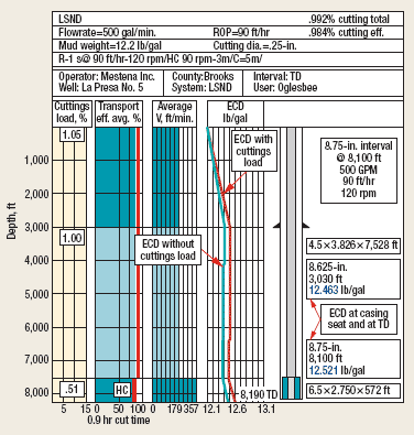
The hydraulic model was run again with an ROP of 90 ft/hr and a pump rate of 500 gpm, this time simulating conditions at 8,500-ft TD, the planned depth of the well. The ECDs increased over static mud density by 0.099 ppg and 0.109 ppg at the casing seat and TD, respectively, while the cuttings loading remained steady at about 1%, Fig. 5. This set of drilling parameters, in combination with the LSND freshwater mud system, provided the best hydraulic option for maximizing drilling efficiency while preventing induced losses in the weak zones.
 |
|
Fig. 5. At 500 gpm and 90 ft/hr the hydraulics prediction increased ECDs by 0.099 ppg and 0.109 ppg at the casing seat and TD.
|
|
Thorough hydraulics modeling using actual mud pump and drillstring specifications-as well as realistic mud properties-demonstrated that a flow rate of 500 gpm would reduce the ECD, while still providing more than adequate hole cleaning in the 83/4-in. interval.
The second part of the engineered approach to the La Presa 5 drilling fluid included further modeling to determine optimal LCM types and particle size distribution. Information from the first three La Presa wells was used to prepare LCM treatments for the La Presa 4, but the conventional lignosulfonate mud in use on that well made it difficult to control ECD once LCM was added to the system. The well lost complete returns at 6,902 ft.
Although an additional LCM treatment was able to restore circulation, the 7-in. intermediate casing was run on the La Presa 4 at 7,000 ft. The production interval was drilled with a 61/8-in. bit to 8,000 ft, where the drillstring became stuck. It was necessary to pump a spotting fluid and work the pipe for about one day. The pipe came free and the well reached TD at 8,100 ft. A total of 16 days were required from spud to setting and cementing production casing.
Based on results obtained from specialized modeling used to analyze the lost circulation potential in the La Presa 5, drilling-fluids personnel determined that 15-bbl sweeps pumped at each connection would help minimize losses and prevent fracture propagation, if the sweeps were formulated with the right concentrations and types of LCM. Given the rock characteristics and probable fracture widths in the thief zone, the drilling-fluids technical team modeled the Vicksburg formation against a wide range of LCM types and particle sizes.
The final LCM treatment recommended for the La Presa 5 contained two materials:
1. A resilient graphitic carbon material at 2.0 lb/bbl. This deforms into the fracture shape as pressure increases and returns to its original shape when pressure decreases without becoming dislodged.
2. Two relatively coarse grades of sized calcium carbonate at 15 lb/bbl each. This treatment recommendation was based on input data such as Young’s modulus and Poisson’s ratio. The final particle size distribution was designed to minimize the rheology impact and ECD made by adding the LCM mix.
The sweep program was initiated at 6,280 ft, just above the thief zone. Rigsite drilling-fluids personnel monitored the mud properties to ensure that gel strengths were as low as possible without sacrificing suspension qualities and used plastic viscosity values as the indicator for solids content.
Continuing to use modeling based on actual drilling parameters at the La Presa 5 rigsite, drilling-fluids personnel maintained a close watch on hydraulic data and mud properties, making minor modifications as needed. Surge pressures while tripping and running casing remained within safe parameters. Breaking circulation after several static periods for rig repair produced nearly imperceptible pressure spikes, as compared with conventional dispersed mud systems. The scheduled sweeps, formulated with sized calcium carbonate and fine-ground resilient graphitic material, provided effective sealing and bridging through the thief zone.
CONCLUSION
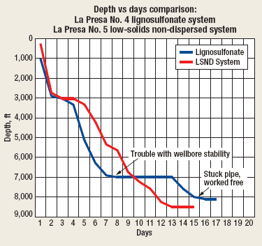
Production casing was set and cemented on the La Presa 5 well at the planned 8,500-ft TD with a mud density of 12.0 ppg in 15 days. The intermediate casing was not required. By comparison, the La Presa 4 production interval was cased and cemented at 8,100 ft in 16 days and required a 7-in. intermediate casing string, Fig. 6.
 |
|
Fig. 6. Depth vs. days comparison between the two wells and mud systems shows the improved performance of the LSND approach to lost circulation.
|
|
The risk factors for NPT were mitigated by running a very clean, low-solids system and constantly monitoring ECD values with hydraulics modeling software. After completing successful wireline logging operations, the operator set and cemented production casing. No mud losses were experienced while drilling, running casing or cementing on the La Presa 5. 
ACKNOWLEDGMENT
The authors thank Mestena Operating for permission to publish this article and to the drilling fluid modelers and crews that successfully guided drilling through the difficult Vicksburg thief zone.
|
THE AUTHORS
|
| |
Brannon Slusher has a BS degree in natural gas engineering from Texas A&M University-Kingsville and will receive an MBA from Texas A&M University-Corpus Christi this year. He has more than 14 years’ experience in the oil and gas industry, is a registered professional engineer and is the vice president of Mestena Operating, Ltd. in Corpus Christi, Texas.
|
|
| |
Jim Oglesbee has more than 27 years’ experience in the drilling fluids industry in drilling theaters worldwide, providing both advanced technical planning and onsite operational support. Oglesbee is an account representative for Halliburton Fluid Services and is based in Corpus Christi, Texas.
|
|
| |
Alfredo Villarreal has a Bachelor of Applied Arts and Science from the University of the Incarnate Word and has 11 years’ experience. He started as field service representative, worked in and later supervised the Halliburton Baroid Fluid Service Lab in Alice, Texas. Villarreal is an operations leader with Halliburton Fluid Service and is based in Corpus Christi, Texas.
|
|
|


